


4
1
•
Flexible connections suitably selected for the fluid and pressure involved should be provided as mandatory in order to
minimize transmission of vibrations to the piping / building as some movement of the unit can be expected during
normal operation. The piping and fittings must be separately supported to prevent any loading on the cooler.
•
The cooler must be protected by a strainer, preferably of 20 mesh, fitted as close as possible to the liquid inlet connec-
tion, and provided with a means of local isolation.
•
Thermometer and pressure gauge connections should be provided on the inlet and outlet connections of each cooler.
Pressure gauges are recommended to check the water pressure before and after the cooler and to determine if any
variations occur in the cooler and system. When installing pressure taps to measure the amount of pressure drop
across the water side of the cooler, the taps should be located in the water piping a minimum of 24 inches downstream
from any connection (flange etc.) but as near to the cooler as possible.
•
Drain and air vent connections should be provided at all low and high points in the piping system to permit complete
drainage of the cooler and piping as well as to vent any air in the pipes. Hand shut-off valves are recommended for use
in all lines to facilitate servicing.
•
The system water piping must be flushed thoroughly before connecting to the unit cooler. The cooler must not be
exposed to flushing velocities or debris released during flushing. It is recommended that a suitably sized bypass and
valve arrangement is installed to allow flushing of the piping system. The bypass can be used during maintenance to
isolate the cooler without disrupting flow to other units.
•
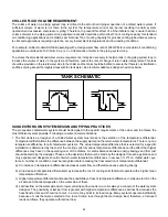
The following is a suggested piping arrangement at the chiller for single unit installations. For multiple chiller installa-
tions, each unit should be piped as shown:
Note
: For chillers with two coolers, the connecting pipes for entering and leaving water on one cooler must be joined to
the corresponding pipes on the other cooler before connecting to the main headers in the system piping.
OUT
IN
Isolating Valve - Normally Open
Isolating Valve - Normally Closed
Balancing Valve
Flow meter
Strainer
Pressure tapping
Flow Switch
Connection (flanged / Victaulic)
Pipe work
Flexible connection
Содержание ASQ Series
Страница 1: ......
Страница 2: ......
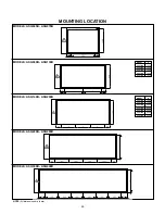
Страница 24: ...24 ASQ115B ASQ130B ASQ140B ASQ150B DIMENSIONS NOTE ALL DIMENSIONS ARE IN MILLIMETERS UNLESS OTHERWISE SPECIFIED...
Страница 27: ...27 DIMENSIONS ASQ300B ASQ320B ASQ330B ASQ340B NOTE ALL DIMENSIONS ARE IN MILLIMETERS UNLESS OTHERWISE SPECIFIED...
Страница 30: ......
Страница 50: ......