3
6
COOLER FREEZE PROTECTION
If the unit is located in an area where ambient temperatures fall below 32
0
F (0
0
C), cooler protection in the form of Ethylene
Glycol Solution is required to protect the cooler and fluid piping from low ambient freeze-up. This glycol solution must be
added to the water system loop to bring down the freezing point of water to a difference of 15
0
F (8.3
0
C) below minimum
operating ambient temperature.
Using this glycol solution causes a variation in unit performance, flow rate and pressure drop, therefore appropriate
correction factors from the aforementioned table in this catalog should be applied.
MULTIPLE CHILLER ARRANGEMENT OR PLANT CONFIGURATION
A multiple chiller system has two or more chillers connected by parallel or series piping to a common distribution system.
Multiple chiller arrangements offer the advantage of operational flexibility, standby capacity and less disruptive mainte-
nance. Also, they offer some standby capacity if repair work must be done on a chiller from a set of duty chillers. Starting
in-rush current is reduced, as well as power costs at partial-load conditions.
A multiple chiller arrangement should be provided if the system load is greater than a single chiller capacity, standby
capability is desired, large temperature drop (greater than 15
0
F) is desired or application calls for splitting the total
capacity for better part load operation.
In designing a multiple chiller plant, units of same size should be preferred over different sizes to facilitate balanced water
flow. It is mandatory that cooler flow rates must be balanced to ensure proper flow to each chiller based on its respective
capacity. As mentioned above, two basic multiple chiller systems are used: parallel and series chilled water flow.
In the parallel arrangement, liquid to be chilled is divided among the liquid chillers; the multiple chilled streams are
combined again in a common line after chilling. Water temperatures (EWT or LWT) can be used to cycle units On and Off
based on the cooling demand. Parallel arrangements permit adding chillers in the future for plant expansion with the
appropriate considerations beforehand.
In the series arrangement, the chilled liquid pressure drop may be higher unless coolers with fewer liquid-side passes or
baffles are used. No over chilling by either unit is required, and compressor power consumption is lower than it is for the
parallel arrangement at partial loads. It is also possible to achieve higher overall entering to leaving temperature drops,
which may in turn provide the opportunity for lower chilled water design temperature, lower design flow and resulting
installation and operational cost savings. Series chiller arrangements can be controlled in several ways based on the
water temperatures depending on cooling demand.
A valved piping bypass is suggested around each chiller to facilitate future servicing as it gives the personnel an option
for service without a complete shutdown.
COOLINE recommends the parallel arrangement for design temperature drops (
∆
T) up to 15
0
F and the series arrange-
ment beyond that i.e., 16 to 20
0
F. Complete design details on these parallel and series chilled water flow arrangements
can be found in the ASHRAE handbooks and other design literature which should be referred by the designer in preparing
his detailed designs.
PIPING ARRANGEMENTS AND PLANT LAYOUT
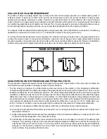
Our chillers are suitable for incorporating in ‘Two Pipe’ single temperature systems or ‘Four Pipe’ independent load
systems. The system piping circuit (load distribution circuit) should be basically parallel piping either Direct Return or
Reverse Return system with a good pumping arrangement.
The method of circuiting and pumping is a judgment decision by the designer. The designer must weigh the pros and
cons of cost, nature of load and configuration of building, energy economics, flexibility, installation requirements and
others to determine the best arrangement for his project. In all cases, it must be ensured that the design water flow is
constantly maintained through the chillers at all stages of operation. Some suggested arrangements with basic sche-
matic layouts are as follows:
Содержание ASQ Series
Страница 1: ......
Страница 2: ......
Страница 24: ...24 ASQ115B ASQ130B ASQ140B ASQ150B DIMENSIONS NOTE ALL DIMENSIONS ARE IN MILLIMETERS UNLESS OTHERWISE SPECIFIED...
Страница 27: ...27 DIMENSIONS ASQ300B ASQ320B ASQ330B ASQ340B NOTE ALL DIMENSIONS ARE IN MILLIMETERS UNLESS OTHERWISE SPECIFIED...
Страница 30: ......
Страница 50: ......


