3
DB IO&M
B51131-002
Belt and Pulley Installation
Belt tension is determined by the sound of the belts when
the fan is first started. The belts will produce a loud squeal,
which dissipates after the fan is operating at full capacity.
If belt tension is too tight or too loose, lost efficiency and
damage can occur.
Do not change the pulley pitch diameter to change ten
-
sion. The change will result in a different fan speed.
Models SDB
1. Loosen the motor plate bolts and move the motor plate
(with motor installed) so that the belts can easily slip
into the grooves on the pulleys. Never pry, roll or force
the belts over the rim of the pulley.
2. Adjust the motor plate until proper tension is reached.
For proper tension, a deflection of approximately 1/4”
per foot of center distance should be obtained by firm
-
ly pressing the belt. Refer to
Figure 1
.
3. Lock the motor plate adjustment nuts in place.
4. Ensure pulleys are properly aligned. Refer to
Figure 2
.
1 foot
1/4 inch
Figure 1
All Other Fans
1. Loosen the pivoting motor base bolts and turn the ad-
justment screws to lower the motor base so that the
belts can easily slip into the grooves on the pulleys. Nev-
er pry, roll or force the belts over the rim of the pulley.
2. Adjust the motor plate until proper tension is reached.
For proper tension, a deflection of approximately 1/4”
per foot of center distance should be obtained by firm
-
ly pressing the belt. Refer to
Figure 1
.
3. Lock the motor plate adjustment nuts in place.
4. Ensure pulleys are properly aligned. Refer to
Figure 2
.
Figure 2
OFFSET
ANGULAR
OFFSET/ANGULAR
A
W
X
Y
Z
B
CENTER
DISTANCE
(CD)
GAP
GAP
Tolerance
Center Distance
Max.
Gap
Up through 12”
1/16”
12” up through 48”
1/8”
Over 48”
1/4”
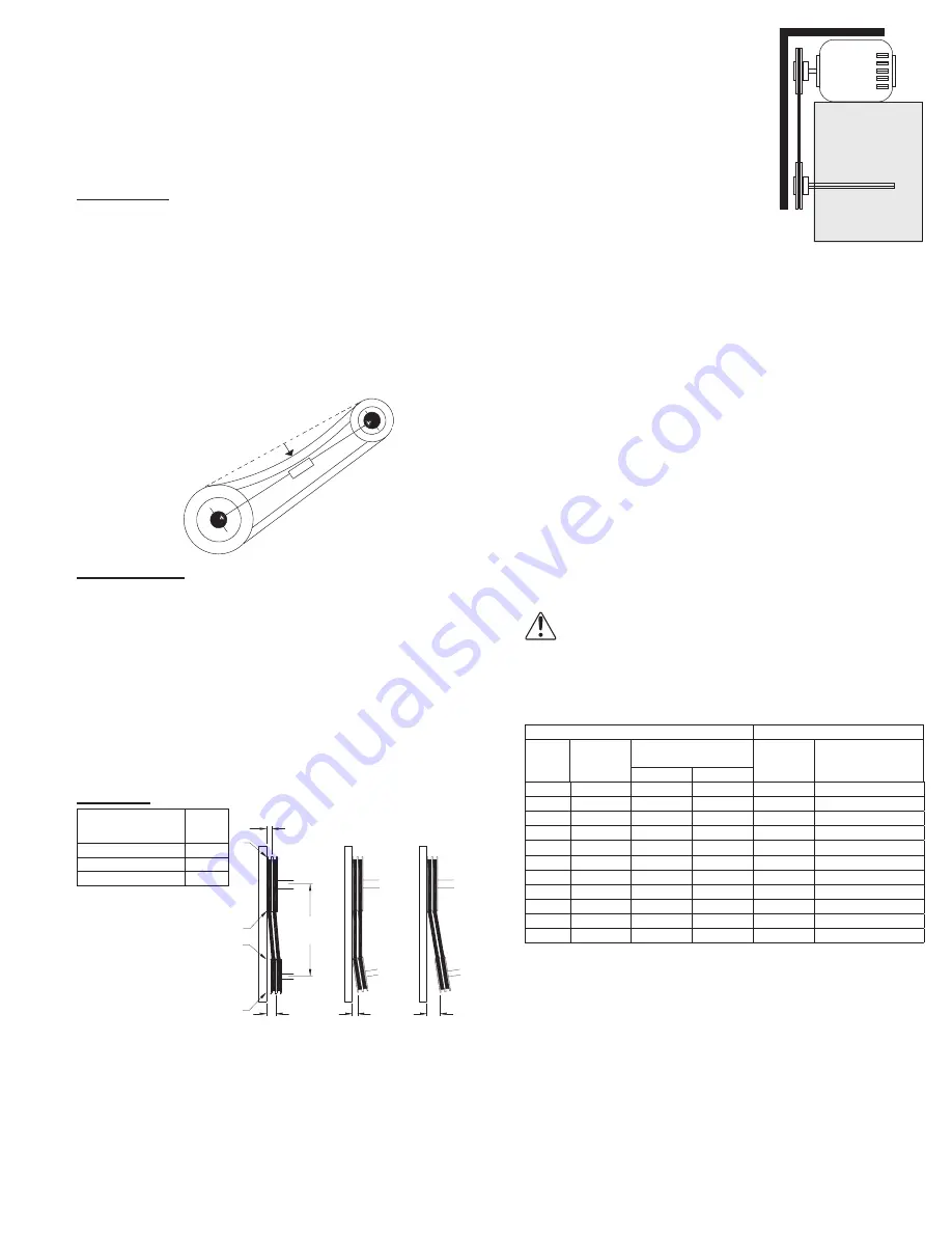
Pulley Alignment
Pulley alignment is adjusted by
loosening the motor pulley set-
screw and by moving the motor
pulley on the motor shaft.
Figure 2
indicates where to mea-
sure the allowable gap for the drive
alignment tolerance. All contact
points (indicated by WXYZ) are to
have a gap less than the tolerance
shown in the table. When the pul-
leys are not the same width, the al-
lowable gap must be adjusted by half of the difference in
width.
Figure 3
illustrates using a carpenter’s square to ad-
just the position of the motor pulley until the belt is parallel
to the longer leg of the square.
Final Installation Steps
1. Inspect fasteners and setscrews, particularly fan
mounting and bearing fasteners, and tighten accord-
ing to the recommended torque shown in the table,
Recommended Torque for Setscrews/Bolts
.
2. Inspect for correct amperage and voltage with an am-
meter and voltmeter.
3. Ensure blower is secured to duct work.
4. Ensure all accessories are installed.
5. Inspect wheel-to-inlet clearance.
6. Test the fan to be sure the rotation is the same as indi-
cated by the arrow marked
Rotation
.
NOTICE! Do not allow the fan to run in the wrong
direction. This will overheat the motor and cause
serious damage. For 3-phase motors, if the fan is
running in the wrong direction, check the control
switch. It is possible to interchange two leads at
this location so that the fan is operating in the cor
-
rect direction.
Recommended Torque for Setscrews/Bolts (IN-LB)
Setscrews
Hold Down Bolts
Size
Key Hex
Across
Flats
Recommended
Torque
Size
Recommended
Torque
Min.
Max.
#8
5/64”
15
21
3/8”-16
324
#10
3/32”
27
33
1/2”-13
780
1/4
1/8”
70
80
5/8”-11
1440
5/16
5/32”
140
160
3/4”-10
2400
3/8
3/16”
250
290
7/8”-9
1920
7/16
7/32”
355
405
1”-8
2700
1/2
1/4”
560
640
1-1/8”-7
4200
5/8
5/16”
1120
1280
1-1/4”-7
6000
3/4
3/8”
1680
1920
-
-
7/8
1/2”
4200
4800
-
-
1
9/16”
5600
6400
-
-
Figure 3


