Contronics DZR-45 Скачать руководство пользователя страница 6

DZR-45

6

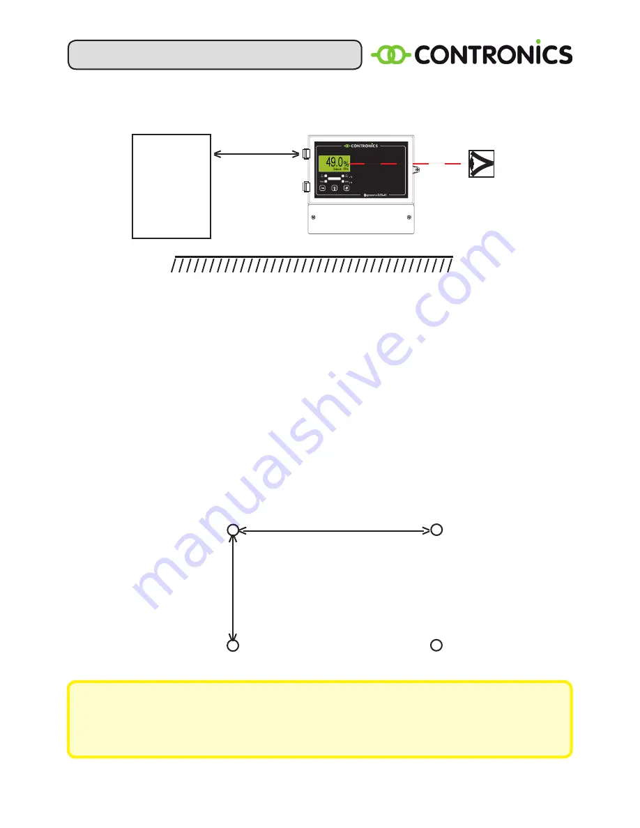
5. WALL-MOUNTING OF THE CONTROLLER

Figure 2. Installation of the controller

The controller must be mounted on an interior wall, preferably in a clean room where 

the humidity level is not excessive. Do not mount the controller above a heating system 

or the like. When installing, ensure that the display is located at eye level and that the 

perforated plate (Fig. 1, item G) is facing downwards. Keep an area of up to 26 cm free 

to the left of the controller to ensure that the cover can be opened (see Fig.2).

Open the cover of the controller by removing the screw from the upper cover (see 

Fig. 1, item D). Remove the cover from the connection compartment (Fig. 1, item J) 

by removing the two retaining screws. There are 4 mounting holes: 2 in the top corners 

of the housing, and 2 at the bottom (Fig. 1, item F). M4 or M5 screws can be used for 

these holes. You will find the hole pattern in the diagram below:

Figure 3. Mounting holes pattern.

At least 26 cm.

Object or 

wall


SET

Hygrozone DZR-45

Made in Holland

Eye level

222 mm

193 mm

IMPORTANT

If you wish to make holes in the perforated plate (Fig. 1, item G), please ensure 

that the cover (J) of the connection compartment is positioned correctly. Then 

carefully make the required number of holes using a hammer. 

Содержание DZR-45

Страница 1: ...24 02 2016 version 1 6 CONTROLLER USER MANUAL DZR 45...

Страница 2: ...int Oedenrode The Netherlands hereby declares that the product DZR 45 produced and delivered by Contronics Engineering B V are in accordance with the following CE directives EMC Directive 2014 30 EU D...

Страница 3: ...TION 4 3 CONTENT OF THE DELIVERY 4 4 DESCRIPTION OF THE CONTROLLER 5 5 WALL MOUNTING OF THE CONTROLLER 6 6 connections 7 7 OPERATION 8 8 SCREEN SETTING 9 9 TECHNICAL DATA 14 10 MENU OVERVIEW 15 11 fac...

Страница 4: ...the proportional control LED indicators for humidification and dehumidification Main switch 230V Touch key operation Bandwidth setting Dead zone setting Maximum minimum setting Offset for the sensors...

Страница 5: ...LEDs C Pushbuttons D Securing screw for the upper cover E On Off switch F Holes for wall mounting G Perforated plate H Mounting screws for perforated plate M4 x 8mm I Screws for the connection compart...

Страница 6: ...er of the controller by removing the screw from the upper cover see Fig 1 item D Remove the cover from the connection compartment Fig 1 item J by removing the two retaining screws There are 4 mounting...

Страница 7: ...1 RH 7 Not used 8 Yellow Sensor 1 HS 91 temperature 9 Green Sensor 1 HS 91 0V HS 10 connections Connection Colour Description 5 Brown Sensor 1 HS 10 12V 7 White Sensor 1 HS 10 RH 9 Green Sensor 1 HS 1...

Страница 8: ...idifier also uses energy 10 Watt and water rinse program in the stand by posi tion 230V switched on no humidity generation You can reduce this by switching off the humidification completely if the RH...

Страница 9: ...main screen Figure 6 Main screen Figure 7 sensor screen Language setting Press SET Scroll to System using the or button Press SET Scroll to Language using the or button Press SET Select the language...

Страница 10: ...ontrol Double hygrostat In principle this is the same as 2 single hygrostats The regulation of dehumidification is hereby not possible The output of hygrostat 2 uses the dehumidification output Two hy...

Страница 11: ...rt time and Stop time setting is used to indicate the time within which the block will be active The Fluid type setting can as an option be used to switch between different fluids via an electrical va...

Страница 12: ...igured Sub configuration Mode Hygrostat Standard hygrostat function with set value Hygrostat 1 2 humidity set point Capacity Provides a fixed output value Hygrostat 1 2 Capacity Hygrostat Capacity The...

Страница 13: ...temperature Sensor selection The sensor used sensor 1 or sensor 2 Mode Cooling Relay 3 will be activated if the current temperature is above the set value Heating Relay 3 will be activated if the cur...

Страница 14: ...al menu not accessible Only available in double hygrostat configuration 9 TECHNICAL DATA Supply voltage 230V 10 50 60 Hz Maximum relay load 8A 250 VAC Proportional outputs 0 10V 2x General accuracy 20...

Страница 15: ...Humidification bandwidth Maximum humidification Minimum humidification Sensor selection Maximum humidification Sensor selection Bandwidth Modus Dead zone Humidification Humidification bandwidth Maxim...

Страница 16: ...0 2 0 C Humidification bandwidth 1 20 3 Minimum humidification 0 100 0 Maximum humidification 0 100 100 Dehumidification bandwidth 1 20 3 Minimum dehumidification 0 100 0 Maximum dehumidification 0 10...

Страница 17: ...Alarm Minimum humidity Off 5 94 Off Maximum humidity Off 6 95 Off Minimum Temperature Off 39 121 Off C Maximum Temperature Off 38 122 Off C Alarm delay 0 240 0 min Sensor set tings Sensor type Humidit...

Страница 18: ...is 1 HS 91 HK 01 Network cable Figure 10 Connection diagram single hygrostat Electrical distribution board 1 2 9 8 7 6 5 4 3 13 12 11 10 C C C C NO NO NO NC NC NO L L N Relais 4 Relais 3 Relais 2 Rela...

Страница 19: ...91 HK 01 Network cable Sensor 1 HS 91 Sensor 2 Figure 12 Connection diagram hygrostat with maximun control Electrical distribution board 1 2 9 8 7 6 5 4 3 13 12 11 10 C C C C NO NO NO NC NC NO L L N R...

Страница 20: ...distribution board 1 2 9 8 7 6 5 4 3 13 12 11 10 C C C C NO NO NO NC NO NC L L N Relais 4 Relais 3 Relais 2 Relais 1 HS 91 HK 01 Network cable Figure 14 Connection diagram for optimization of energy a...

Страница 21: ...e at http www contronics nl support software doenloads 2 Unpack the Zip archive and run Setup exe 3 Follow the instructions in the installation wizard 4 Connect the DZR 45NET to your network 5 Connect...

Страница 22: ...application Figure 16 Manage devices 3 Check the Active checkbox of the devices on the network that need to be controlled from this application 4 Set the network properties of each device by selecting...

Страница 23: ...that is easy to refer to 6 The Ethernet module reboots after changing properties and becomes available again within 30 seconds Figure 18 Manage devices 7 Manage devices shows a list of connected devic...

Страница 24: ...nd feel By clicking on the buttons on the right the user gets access to more information and settings Info Displays network MAC address together with soft and hardware version Settings Change all sett...

Страница 25: ...d By selecting a different month historical data can be shown in the graph Updates The Network Application will check for updates each time the application is launched and the user can choose to downl...

Страница 26: ...DZR 45 26...

Страница 27: ...oducts We therefore reserve the right to modify the design construction and technology of the product at any time For this reason no claims can be made based on the data illustrations and description...

Страница 28: ...DZR 45 28 P O Box 144 5490 AC Sint Oedenrode The Netherlands Telephone 31 0 413 487000 Telefax 31 0 413 473903 Website www contronics nl E mail info contronics nl...

Отзывы: