background image

33

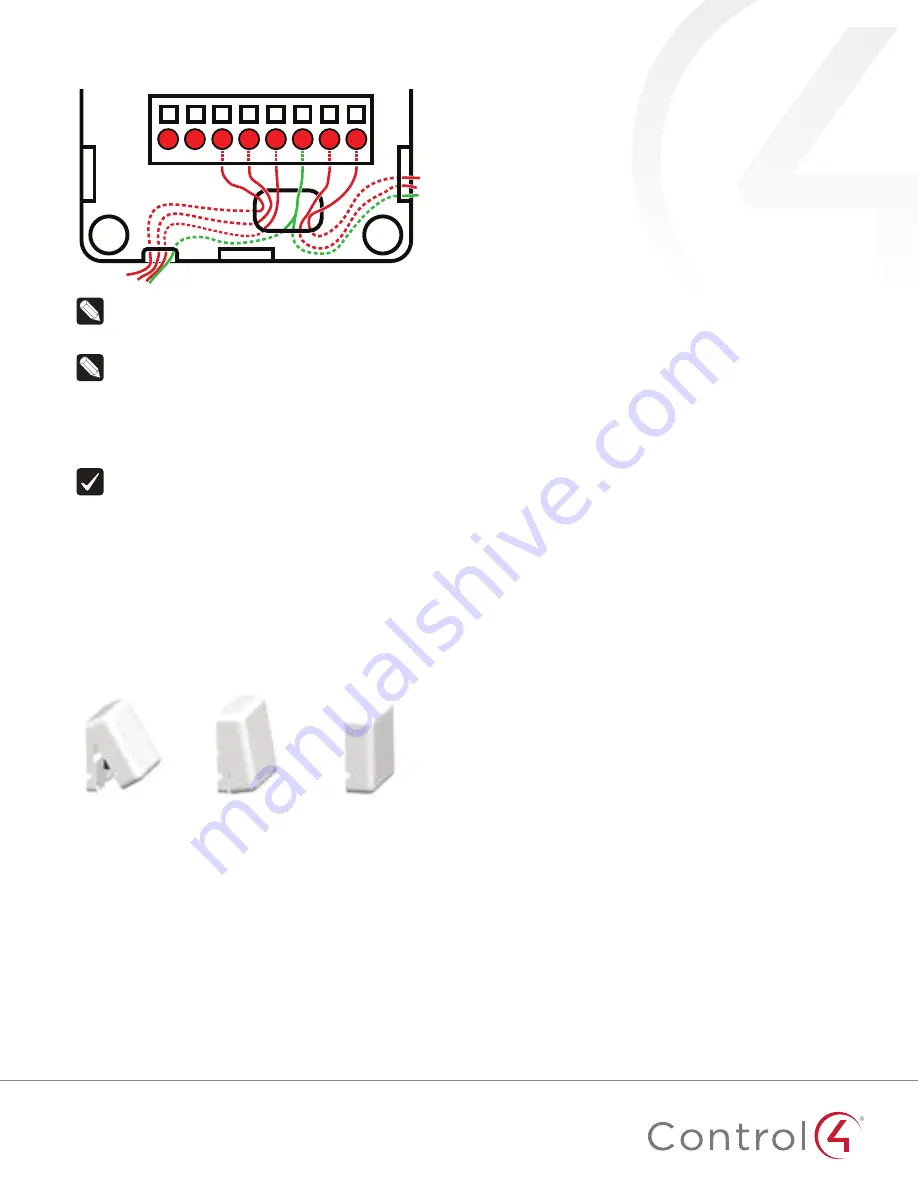
Thread any contact or thermistor wires from the wall through 

the openings in the tray and to the terminal block.

T

C1

C2

Cm

C3

C4

VO Cm

Note: 

The two 

Cm

 (common/ground) pins are 

connected and can be used interchangeably.

Insert and tighten the mounting screws.

Note: 

You may optionally choose to use robust two-

sided tape to mount the tray assembly to the wall or 

other flat surface, as long as the tape won’t prevent the 

back of the tray from sitting flush against the mounting 

surface.

10 

Connect the wires from the tray to the terminals in the cover, 

matching the proper wires to the target terminal locations.

Important! 

When using multiple external contact 

sensors, or when using an external contact sensor along 

with an external thermistor, you 

must 

connect each 

device to one of the Common (Cm) pins in addition 

to the appropriate sensor or thermistor pin to make 

a proper wiring connection. See the “Sample wiring 

configurations” section of this document for examples.

11 

Attach the cover assembly to the tray: 

Align the side of the cover with the side of the tray, 

engaging the plastic tabs with the corresponding holes. 

Rock the cover into place, snapping it to the tray.

Press firmly on the bottom center edge of the cover to 

snap and lock it to the tray assembly.

a.

 Align the cover edge’s 

two latching tabs with 

corresponding tab 

receivers on the tray’s 

edge.

b.

 Close the cover by 

rocking it toward the 

other end of the tray.

c.

 Press firmly on the 

center edge of the 

cover until it snaps and 

locks into place with 

the tray.

Configuring

To configure your device:

Add the device to your Composer Pro project. When 

prompted to identify the device, press the 

ID

 button on the 

face of the cover four times. The green LED blinks twice to 

confirm the ID has been sent to the Control4 system.

- OR -

In Composer Express, add a device into the project, scan for 

ZigBee devices, then press the ID button on the face of the 

cover four times. 

In the driver’s 

Properties 

tab, view or configure the settings 

explained below under “Properties,” then click 

Set 

to the 

right of the setting after each change.

Add generic contact drivers (such as 

Door Contact Sensor

Gate

, and 

Motion Sensor

) in 

System Design

 view, then 

connect the generic driver to the appropriate connection on 

the C4-Z2C device in 

Connections

 view.

For programming, use these events:

• 

Missed Checkin: 

Triggers when the device misses a 

controller check in for the number of times specified in 

the driver’s “Missed Checkin Limit” setting.

• 

Online: 

Triggers when the device comes online.

• 

Offline:

 Triggers when the device goes offline.

• 

Reboot:

 Triggers when the device reboots.

Properties

General properties

• 

Log Level:

 Standard for most drivers, this property 

allows you to filter which message types display in the 

Lua Output

 window. Options 0 - 5 correspond to Fatal 

through Trace levels, increasing in level of verbosity. 

Options are 0=Fatal, 1=Error, 2=Warning, 3=Info, 4=Debug, 

and 5=Trace. Default is 

1 - Error

• 

Log Mode:

 Activates logging of diagnostic information. 

The log level is set in the above property. Options include 

Off

Print

 (to the window), 

Log

 (to the Director Log), and 

Print and Log

 (both). Default is 

Off

• 

Driver Version:

 (Read only) Shows the version number of 

the driver currently in use. 

• 

Device Status:

 (Read only) Shows the current status of 

the product, whether online or offline. However, in some 

cases, the device may not report its status immediately, 

such as when the device is rebooting. 

• 

Firmware Version: 

(Read only) Shows the version 

number of the firmware currently in use on the device. 

The firmware will be updated automatically over the air 

when the Control4 OS is updated and when that update 

includes a new firmware version for this device. 

• 

Bootloader Version:

 (Read only) Shows the version 

number of the firmware currently in use on the device. 

The bootloader can only be updated by Control4, so this 

property is for support/diagnostic information only. 

Battery properties

• 

Battery Level: 

Reports the charge level of the battery. 

When the batteries on a Z2C are low, a low battery alert 

can be configured using the Z2C’s battery level. When the 

batteries are very low, the LED behavior and temperature 

and humidity reporting become unreliable.

Humidity properties

• 

Local Humidity:

 (Read only) Shows the relative humidity 

measured where the device is located. The value is shown 

as a percentage. 

• 

Local Humidity Offset:

 The humidity sensor provides 

accuracy of +/- 4% relative humidity. Adjusting the 

Local Humidity Offset

 can result in increased inaccuracy 

of relative humidity reporting without using humidity 

calibration equipment for validation.

Содержание C4-Z2IO

Страница 1: ...or IR cables can be spliced together in parallel not in series to increase the number of controlled devices Be aware that these connected emitters cannot be controlled independently but will all fire...

Страница 2: ...e acts as a ZigBee mesh extender and router It is designed to extend the ZigBee network into distant or hard to reach areas The Z2IO provides support for up to 32 nodes in its ZigBee routing table Thi...

Страница 3: ...e with any water based residential paints Do not clog the cover assembly vent holes with paint Accessories External thermistor ZCA EXT10A AC DOTS1 W AC PMT51 W Installing 1 Place the device in a locat...

Страница 4: ...f the cover until it snaps and locks into place with the tray 12 For ZigBee to IR connect any IR emitters to the two IR ports then affix the emitter head to the IR window on the device to control such...

Страница 5: ...Sets which scale is used to calculate the temperature used in the Local and Remote Temperature properties described below and affects only the Properties tab s settings Options include Fahrenheit and...

Страница 6: ...e action buttons will trigger the corresponding relay to open Troubleshooting If the device is not working Reboot the device by disconnecting power then re connecting power Check for proper wiring See...

Страница 7: ...he humidistat senses humidity from 5 to 90 The device checks the temperature and humidity every five minutes If the temperature has changed more than 0 9 F 0 5 C the device reports the new temperature...

Страница 8: ...vice in a location which ensures the following Easy access to any externally connected wires ZigBee mesh networking efficiency Note Make sure the device has good ZigBee wireless reception by 1 ensurin...

Страница 9: ...Design view then connect the generic driver to the appropriate connection on the C4 Z2C device in Connections view 4 For programming use these events Missed Checkin Triggers when the device misses a c...

Страница 10: ...checked in with the controller Missed Checkin Limit Sets the number of times the checkin is missed before triggering the Missed Checkin programming event Actions tab Buttons located on the Actions tab...

Страница 11: ...latory Safety information To review Regulatory information for your particular Control4 products see the information located on the Control4 website at ctrl4 co reg Patent information Applicable paten...

Страница 12: ...e on a device that can view PDFs DATA SHEET ctrl4 co z2io ds MOST RECENT VERSION ctrl4 co z2io ig Regulatory Safety information To review Regulatory information for your particular Control4 products s...

Страница 13: ...ventilation Installer conform ment aux instructions du fabricant 8 Do not install near any heat sources such as radiators heat registers stoves or other apparatus including amplifiers that produce he...

Страница 14: ...ord or plug is damaged liquid has been spilled or objects have fallen into the apparatus the apparatus has been exposed to rain or moisture does not operate normally or has been dropped 14 Confiez tou...

Страница 15: ...cal equipment such as tape recorders TV sets radios computers and microwave ovens if placed in close proximity 19 Ce produit peut interf rer avec des appareils lectriques tels que les magn tophones t...

Страница 16: ...equipment and receiver Connect the equipment into an outlet on a circuit different from that to which the receiver is connected Consult the dealer or an experienced radio TV technician for help FCC Pa...

Страница 17: ...fication number signifies that FCC and Industry Canada technical specifications were met FCC ID R33C4Z2IO IC 7848A C4Z2C This equipment must be installed by qualified professionals or contractors in a...

Страница 18: ...Les utilisateurs finaux doivent suivre les instructions de fonctionnement sp cifiques pour satisfaire la conformit aux expositions RF L quipement ne doit tre utilis ou install des endroits o il est n...

Страница 19: ...e Council Directive s is declared EMC 2014 30 EU Electromagnetic Compatibility EMC Directive Emissions EN 55032 2012 Immunity EN 55024 2010 A1 2015 EN 61000 3 2 2014 EN 61000 3 3 2013 Safety 2006 95 E...

Страница 20: ...Conseil s est d clar e EMC 2014 30 compatibilit lectromagn tique CEM UE missions EN 55032 2012 immunit EN 55024 2010 A1 2015 EN 61000 3 2 2014 EN 61000 3 3 2013 S curit 2006 95 CE Directive Basse Tens...

Страница 21: ...st EMC 2014 30 EG Elektromagnetische Vertr glichkeit EMV Die Richtlinie Emissionen EN 55032 2012 Immunit t EN 55024 2010 A1 2015 EN 61000 3 2 2014 EN 61000 3 3 2013 Sicherheit 2006 95 EG Niederspannun...

Страница 22: ...ompatibilit elettromagnetica EMC Emissioni EN 55032 2012 immunit EN 55024 2010 EN 301 489 1 v1 9 2 2011 09 EN 301 489 17 V2 2 1 2012 09 EN 61000 3 2 2006 A1 2009 A2 2009 e EN 61000 3 3 2008 Sicurezza...

Страница 23: ...de compatibilidad electromagn tica EMC Emisiones EN 55032 2012 inmunidad EN 55024 2010 EN 301 489 1 v1 9 2 2011 09 EN 301 489 17 V2 2 1 2012 09 EN 61000 3 2 2006 A1 2009 A2 2009 e EN 61000 3 3 2008 S...

Страница 24: ...idade Electromagn tica EMC Emiss es EN 55032 2012 Imunidade EN 55024 2010 EN 301 489 1 v1 9 2 2011 09 EN 301 489 17 V2 2 1 2012 09 EN 61000 3 2 2006 A1 2009 A2 2009 e EN 61000 3 3 2008 Seguran a 2006...

Страница 25: ...Electrical and Electronic Equipment WEEE directive 2012 19 EC The WEEE directive requires the manufacturers of electrical and electronic equipment who sell in EU countries 1 label their equipment to n...

Отзывы: