


Protected under U.S. Patents 7,335,845, 7,106,261 and licensed under U.S. Patents
5,905,442 and 5,982,103
About this Document
©2011 Control4. All rights reserved. Control4, the Control4 logo, the Control4 iQ logo
and the Control4 certified logo are registered trademarks or trademarks of Control4
Corporation in the United States and/or other countries. All other names or brands may
be claimed as property by their respective owners. Pricing and specifications subject to
change without notice.
Part Number: 200-00164 Rev H 3/04/2011
Recycling
For information about Control4’s recycling program, go to:
www.control4.com/recycling.
Warranty
Limited 2-year Warranty. Refer to http://www.control4.com/warranty.
Third-Party Trademarks
Libertas
Libertas Firmware copyright statement for Touch Screens 6/26/09
Copyright (c) 2006, One Laptop per Child and Marvell Corporation.
All rights reserved.
Redistribution. Redistribution and use in binary form, without modification, are permitted
provided that the following conditions are met:
* Redistributions must reproduce the above copyright notice and the following disclaimer
in the documentation and/or other materials provided with the distribution.
* Neither the name of Marvell Corporation nor the names of its suppliers may be used
to endorse or promote products derived from this software without specific prior written
permission.
* No reverse engineering, decompilation, or disassembly of this software is permitted.
* You may not use or attempt to use this software in conjunction with any product that is
offered by a third party as a replacement, substitute or alternative to a Marvell Product
where a Marvell Product is defined as a proprietary wireless LAN embedded client solu
-
tion of Marvell or a Marvell Affiliate.
DISCLAIMER. THIS SOFTWARE IS PROVIDED BY THE COPYRIGHT HOLDERS AND
CONTRIBUTORS “AS IS” AND ANY EXPRESS OR IMPLIED WARRANTIES, INCLUD
-
ING, BUT NOT LIMITED TO, THE IMPLIED WARRANTIES OF MERCHANTABILITY AND
FITNESS FOR A PARTICULAR PURPOSE ARE DISCLAIMED. IN NO EVENT SHALL
THE COPYRIGHT OWNER OR CONTRIBUTORS BE LIABLE FOR ANY DIRECT,
INDIRECT, INCIDENTAL, SPECIAL, EXEMPLARY, OR CONSEQUENTIAL DAMAGES
(INCLUDING, BUT NOT LIMITED TO, PROCUREMENT OF SUBSTITUTE GOODS OR
SERVICES; LOSS OF USE, DATA, OR PROFITS; OR BUSINESS INTERRUPTION)
HOWEVER CAUSED AND ON ANY THEORY OF LIABILITY, WHETHER IN CONTRACT,
STRICT LIABILITY, OR TORT (INCLUDING NEGLIGENCE OR OTHERWISE) ARISING
IN ANY WAY OUT OF THE USE OF THIS SOFTWARE, EVEN IF ADVISED OF THE
POSSIBILITY OF SUCH DAMAGE.
GNU
GNU GENERAL PUBLIC LICENSE TERMS AND CONDITIONS FOR COPYING, DISTRI
-
BUTION AND MODIFICATION (Section 3.b.)
You may copy and distribute the Program (or a work based on it, under Section 2) in
object code or executable form under the terms of Sections 1 and 2 above provided that
you also do one of the following:
Accompany it with a written offer, valid for at least three years, to give any third party, for
a charge no more than your cost of physically performing source distribution, a complete
machine-readable copy of the corresponding source code, to be distributed under the
terms of Sections 1 and 2 on a medium customarily used for software interchange.
The complete text for this license is available on the Control4 web site at: http://www.
control4.com.
At Security, select
None
,
WEP 64
,
WEP 128
, or
WPA
. At Password, type the
password on the keyboard that appears. Press
Done
.
Select
Connect
. Notice that the IP settings change. The IP address is set to
DHCP by default.
(Optional) If you need to set a static IP address instead, complete the following
steps:
•
On the Network page, press
Static
.
•
Select each box one at a time and type the address:
IP Address
,
Subnet
Mask
,
Default Gateway
,
Preferred DNS
, and
Alternate DNS
. When the
keyboard appears, type the address, and then press
Done
.
Press
OK
to return to the Network page. You can now connect to a Control4
Director running on a Control4 device on the network.
Press
OK
.
e.
f.
g.
h.
3
4
5
Align and slide the back of the Touch Screen into the power box. The Touch Screen is
magnetic and should snap right into place.
(Optional) To secure the Touch Screen inside the power box, remove the tape
covering the bottom security pin (see Figure 9) before attaching the Touch Screen to
the power box.
Note the pinhole on the bottom underside of the Touch Screen’s faceplate. If you ever
need to remove the Touch Screen from the wall, do the following:
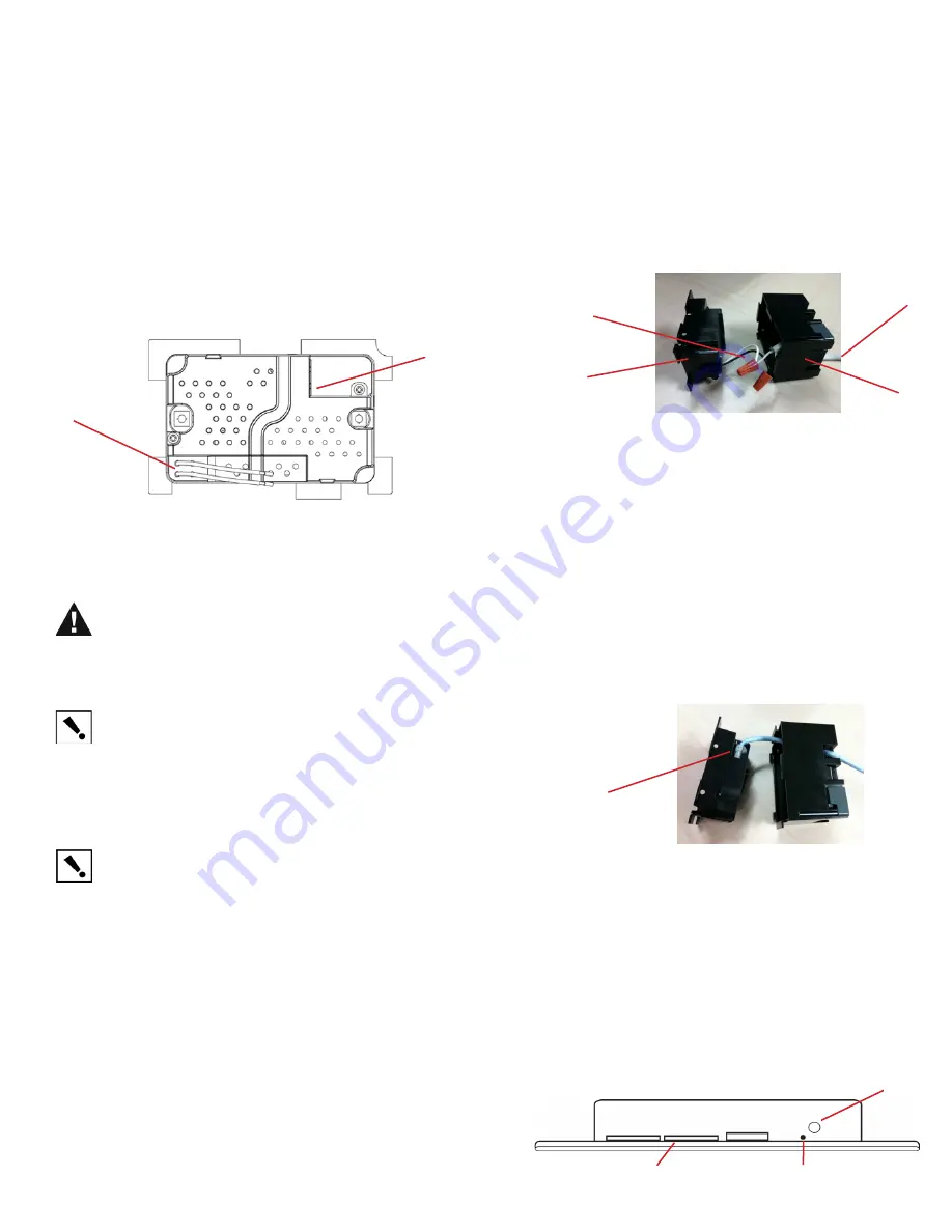
Figure 8. Ethernet Connection
Black and White Wires
a.
b.
Locate the small pinhole on a tab (right side) underneath the Touch Screen.
Insert a paper clip into the hole (about 1/4”). With both hands, lift the Touch
Screen from the bottom of the screen toward you to remove it (see Figure 9).
Figure 9. Touch Screen Pin and Pinhole
AC Power Connection
. The steps below represent a typical U.S. installation.
Connect wires to the AC power source for the Touch Screen according to your
national and local electrical codes. Your installation may require alternative wires and
the use of a terminal block.
a.
b.
c.
Thread the power cable through the bottom back hole of the wall box to the
terminal (Figure 7). Remove the tab covering the hole first.
Using the orange wire nuts (shipped in the box) connect the white-to-white wire
and the black-to-black wire, and then cap each one with a wire nut. Strip the wire
to 1/4” if necessary.
Cap the ground wire from the wall if you are using a plastic wall box. Attach the
ground wire to the wall box when using a metal wall box.
d.
e.
Align and bend the wires carefully to fit them inside the wall box.
Align and carefully slide the power box into the wall box.
Figure 7. AC Power Connection
Regulatory Compliance
FCC/Industry Canada
FCC ID: R33D2 (InfinityEdge 5” In-Wall Touch Screen); R33D3 (InfinityEdge 7” In-Wall
Touch Screen)/Canadian IC: 7848A-D2 (InfinityEdge 5” In-Wall Touch Screen); 7848A-D3
(InfinityEdge 7” In-Wall Touch Screen)
This device complies with Part 15 of the FCC Rules Sub-Part B and C and with
Canada ICES-003 and RSS-Gen. Operation is subject to the following two
conditions: (1) this device may not cause harmful interference, and (2) this device
must accept any interference received, including interference that may cause
undesired operation.
8
When your Touch Screen is physically installed and appears on the home network,
you can add and configure it to the Control4 System using the Composer Pro
software. See the
Composer Pro User Guide
for information about how to add and
identify the Touch Screen to the Control4 System.
IMPORTANT!
Any changes or modifications not expressly approved by the
party responsible for compliance could void the user’s authority to operate this
equipment.
Australia/New Zealand Compliance
•
AS/NZS CISPR 22:2006
Installation
WARNING!
For the location where you are installing the Touch Screen, switch off
the circuit breaker or remove the fuse from the fuse box.
Avertissement!
Pour l’endroit où vous installez l’écran tactile, coupez le disjonc
-
teur ou enlevez le fusible de la boîte de fusible.
Warnung!
Für die Position, in der Sie die Berührungseingabe anbringen, den
Circuit breaker ausschalten oder die Sicherung vom Sicherung Kasten entfernen.
IMPORTANT!
When cutting the opening for the wall box, DO NOT cut the open
-
ing too large. Be conservative and cautiously enlarge it as needed.
Important!
En coupant l’ouverture pour la boîte de mur, ne coupez pas
l’ouverture trop grande. Soyez conservateur et agrandissez-avec précaution la
comme nécessaire.
Wichtig!
Wenn Sie die öffnung für den Wandkasten schneiden, schneiden Sie
NICHT die große öffnung zu. Seien Sie konservativ und vergrößern Sie es vorsi
-
chtig, wie gebraucht.
IMPORTANT!
Before you can complete these instructions below, you must have
a Control4 5” or 7” Touch Screen wall box installed according to the documenta
-
tion provided in the wall box kit. See “Accessories” for details.
Important!
En coupant l’ouverture pour la boîte de mur, ne coupez pas
l’ouverture trop grande. Soyez conservateur et agrandissez-avec précaution la
comme nécessaire. Voyez que <<Accessories>>.
Wichtig!
Bevor Sie diese Anweisungen durchführen können, müssen Sie ein
Control4 7 haben“ der Berührungseingaben- Wandkasten, der entsprechend den
Unterlagen angebracht wird, die in den Wandkasteninstallationssatz bereitgestellt
werden. Sehen Sie daß “Accessories.”
Network Options
•
PoE
: The Ethernet network connection is provided through the PoE Injector. No
additional wiring is needed.
•
Standard Ethernet Connection
: Connect the Touch Screen to one of the RJ-45
LAN ports on the gateway/router using the RJ-45 Ethernet cable.
•
WiFi Connection
: The internal WiFi antenna will communicate with the LAN’s WAP.
If the LAN has a WAP set up, no additional wiring is needed.
Power Configurations
•
AC Power
. AC power is used to power the Touch Screen when using an Ethernet
or WiFi network connection.
•
Power Over Ethernet (PoE)
. PoE is used to power the Touch Screen when using
an Ethernet or WiFi network connection.
Power Cable
Wall Box
Power Box
Ethernet Connection
(WiFi only) Connect to a WAP on the Touch Screen (see Figure 10):
7
After initialization, press and
hold the large red 4 on the
center of the Touch Screen
to enter the configuration
screen.
Press the Network button on
the Touch Screen configura
-
tion page. The network con
-
figuration screen displays.
Under Wireless, select
Enable
. If you don’t see the
network you want, select
Other
.
To protect the screen’s display: Use one of the screen-saver options available from
the
More
>
Settings
>
Screen Saver
page.
6
a.
b.
c.
d.
Figure 10. Wireless Configuration
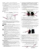
Back View
Figure 6. Back View of InfinityEdge 5” or 7” In-Wall Touch Screen
and Power Box
1
2
1
2
Wireless Connection
: Hot (H) uses Black wire; Return (R) uses White wire.
RJ-45 port for Ethernet Connection
: Ethernet port available for either a standard
Ethernet source that provides network communication only OR a PoE source that
provides power to the device and network communication.
This equipment has been tested and found to comply with the limits for a Class B digital
device, pursuant to Part 15 of the FCC Rules. These limits are designed to provide
reasonable protection against harmful interference in a residential installation. This
equipment generates, uses, and can radiate radio frequency energy and, if not installed
and used in accordance with the instructions, may cause harmful interference to radio
communications. However, there is no guarantee that interference will not occur in a
particular installation. If this equipment does cause harmful interference to radio or televi
-
sion reception, which can be determined by turning the equipment off and on, the user is
encouraged to try to correct the interference by one or more of the following measures:
•
Reorient or relocate the receiving antenna.
•
Increase the separation between the equipment and receiver.
•
Connect the equipment into an outlet on a circuit different from that to which the
receiver is connected.
•
Consult the dealer or an experienced radio/TV technician for help.
Display
: 5” or 7” viewing area, Touch Screen with 800 x 480 resolution.
Shortcut buttons (4)
: For custom programming; to initiate an action or sequence of
actions. Use Composer Pro or Composer HE to configure these buttons.
Touch Screen Removal
: Small hole located under the Touch Screen to remove the
Touch Screen from the wall.
Front dimensions
. 5” Touch Screen (H x W x D): 3.15” x 4.8 x 0.9” (80mm x 122mm
x 23mm); 7” Touch Screen (H x W x D): 4.6” x 6.9 x 0.9” (117mm x 175mm) x 23mm)
Wall box dimensions
. 5” or 7” Touch Screens (H x W x D): 2.7” x 4.1” x 2.4”
(68mm x 104mm x 61mm)
Power box dimensions
. 5” or 7” Touch Screens (H x W x D): 2.8” x 4.5” x 1.8”
(71mm x 114mm x 46mm)
1
2
3
Connect the Control4 PoE Injector to a power source, for example, an AC outlet,
using the power cord (provided with the unit).
Connect one of the RJ-45 LAN ports on the gateway/router/switch to the PoE
Injector’s LAN port using the RJ-45 Ethernet cable.
Connect the PoE Injector’s PWR LAN-OUT port to the RJ-45 Ethernet cable that
will be connected to the Touch Screen.
Pull the Ethernet cable through the top back hole of the wall box to the Ethernet
connector on the top back of the power box, and then connect it (see Figure 8).
Align and carefully slide the power box into the wall box. Unless the Touch
Screen is in the power box, it doesn’t pull any power.
a.
b.
c.
d.
e.
Power Over Ethernet (PoE) Connection
. Install a PoE Injector (sold separately) or
switch, and then connect the PoE Injector to the power and network. Connect to the
power box. The steps below describe how to install a Control4 PoE Injector.
Prepare the plastic power box for installation into the wall box by inserting either the
Ethernet cable or the AC power cable into the power box (see Figures 7 and 8).
1
Secure the power box into the wall box using the screws provided.
Note
: Overtighten
-
ing power box screws could result in a poor connection between the Touch Screen
and the power box.
2
Speaker
Insert paper clip here to
remove Touch Screen
Security pin
Restore the Touch Screen to Factory Default
Press and hold the red
4
button in the top left corner of the screen upon start up, and
follow the instructions presented on the screen to initiate the factory restore process and
to reset the Touch Screen to the factory default settings.
At Network Name, select to add the SSID or wireless network when the keyboard
appears. Select
Done
.


