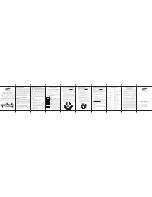
Single Stage, Single Transformer
Dual Stage, Dual Transformer
Pin
1
2
3
4
5
6
7
8
9
10
11
Code
RH
RC
B
G
Y1
Y2
W1
W2
O
TS
TS
Color
Black
Red
Blue
Green
Yellow
Yellow
White
White
Orange
HVAC
Type
Conventional
24VAC Primary
Stage Source
(Heat)
24VAC Second
Stage Source
(Cool)
Damper
Control (Heat)
Fan Relay
Air
Conditioning
Compressor
Control First
Stage
Air
Conditioning
Compressor
Control 2nd
Stage
Furnace
Control
Furnace
Control 2nd
Stage Heat
Damper
Control (Cool)
Remote NTC
Temperature
Sensor
Remote NTC
Temperature
Sensor
Heat Pump
24VAC Primary
Stage Source
(Heat)
24VAC Second
Stage Source
(Cool)
Changeover
Valve (Heat)
Fan Relay
Heat Pump
Primary Stage
Heat Pump
Second Stage
Auxiliary Heat
Heat Pump
Fourth Stage
Changeover
Valve (Cool)
Remote NTC
Temperature
Sensor
Remote NTC
Temperature
Sensor
Sample Wiring Configuration
WARNING!
Do not install LINE VOLTAGE wires to a
LOW VOLTAGE wire.
IMPORTANT!
Do not install any wire to one of the TS
terminals (leading to a remote sensor) other than
supported external temperature sensors (Flush Mount
Remote Temperature Sensor, Aprilaire Model 8051;
or Duct/Outdoor Remote Temperature Sensor,
Aprilaire Model 8052).
NOTE:
Install jumper wire between RC and RH for a
single stage system.
Single Stage, Single Transformer
Dual Stage, Dual Transformer
Connections for Heating, Cooling and Fan
Conventional Systems
Heat Pump Systems