G
F
H
D
E
J
C
B
A
I
A
C
B
D
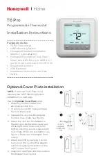
Operation and display
General function
This energy-saving controller for radiators can be used to
control room temperature on the basis of time. The actuator moves
a valve, thereby allowing the amount of heat flowing to the heating
appliance to be controlled. The controller is compatible with all
standard heating appliance valves. A wireless receiver allows the
device to receive commands from taught-in system components.
Installation can be achieved in 3 easy steps.
Step 1: Inserting (replacing) the batteries
Remove the battery compartment
•
cover.
Insert 2 new LR6 batteries (Mignon/AA)
•
into the battery compartment, ensuring
they are the right way round.
Reattach the battery compartment
•
cover and click into place.
New alkaline batteries have a life of approximately two years. A
battery symbol (
) will indicate when the batteries need to
be replaced. After removing the old batteries, please wait ap-
proximately 1 minute before inserting the new ones. This device
does not support operation with rechargeable batteries.
Never recharge standard batteries.
Doing so will present a risk of explosion.
Do not throw the batteries into a fire.
Do not short-circuit batteries.
Used batteries should not be disposed of with
regular domestic waste. Instead, they should
be taken to your local battery disposal point.
Step 2: Setting the date and time of day
The firmware version number will be displayed briefly once you
have inserted/replaced the batteries and then you will be auto-
matically prompted to set the date and time of day.
Use the arrow buttons (B/D) to set
•
the year (A).
Confirm with OK (C).
•
Use the arrow buttons (B/D) to set
•
the month (A).
Confirm with OK (C).
•
Use the arrow buttons (B/D) to set
•
the day (A).
Confirm with OK (C).
•
Use the arrow buttons (B/D) to set
•
the hour (A).
Confirm with OK (C).
•
Use the arrow buttons (B/D) to set
•
the minute (A).
Confirm with OK (C).
•
The motor will start moving back the
control pin while the entries are still being made.
If “INS” is displayed with a rotating “
•
∏” symbol, this indi-
cates that the motor is still moving back. Once the device is
ready for the actuator to be installed on the valve, just “INS”
will appear on the display.
The weekly program and other settings can be custom-
•
ised prior to installation.
To do this, press the menu button
when “INS” is shown on the display. For further details, please
see “4. Configuration menu”.
Once programming is complete, “INS” will reappear on the
•
display and installation (Step 3) can commence.
When “INS” is visible on the display, you can activate the
teach-in function prior to installation by pressing the
button briefly.
Step 3: Installing the energy-saving controller
The actuator can be installed on all standard heating valves.
There is no need to drain away water or fiddle around with the
heating system before doing this. First, you need to remove the
old thermostat dial:
Turn the thermostat dial anti-
•
clockwise as far as it will go (A).
Release the thermal ring of the
•
thermostat (B).
Remove the thermostat from the
•
valve (C).
An adapter will need to be used in
the case of certain valves. Adapters
for Danfoss valves (RA, RAV, RAVL) are included in the scope of
delivery. For details, please refer to
the adapter overview (see 21).
The adapter must be placed on
•
the valve and turned until it is se-
curely seated.
In the case of the RAV adapter,
•
the extension supplied must be
attached to the valve tappet.
The RA and RAV adapters must,
•
in addition, be secured by means
of the bolt and nut supplied.
The energy-saving controller can
only be installed if “INS” is showing on the display. Follow-
ing installation, the actuator will perform an adjustment run so
that it can adapt to the valve. During this process, “ADA” will
be displayed.
Place the actuator on the valve.
•
Tighten the union nut.
•
“INS” will appear on the display, press the OK button.
•
The actuator will perform an adjustment run (“ADA” will appear
•
on the display, operation not possible).
After that, the actuator will be ready for operation (Auto
•
mode).
If the adjustment run was initiated prior to installation, or if
an error message will be displayed (F1, F2, F3); press OK
to move the motor back to the “INS” position.
1. Setting the weekly program
The weekly program allows two separate heating phases (four
switching times) to be set for each day of the week. The pro-
grammed settings only apply to the selected days. Outside these
times the actuator reduces the temperature to the specified set-
back temperature (see 10).
Press and hold down the Menu button for longer than
•
3 seconds.
“PRO” appears on the display.
•
Confirm by pressing the OK button.
•
“DAY” appears on the display. You can use the arrow
•
buttons to select a single day of the week, all weekdays,
the weekend, or the entire week (weekdays has been se-
lected in the example).
Confirm your selection by pressing the OK button.
•
The first heating phase switching
•
time is displayed (6:00); you can
change this time with the arrow
buttons. Heating intervals are also
shown by means of bars.
Confirm by pressing the OK button.
•
You then need to set the tempe-
•
rature that the room should be at
from 6:00 onwards (21.0°C in the
example).
Confirm your selection by pressing the OK button.
•
The end time for the first heating
•
interval is displayed (9:00 in the
example); you can change this time
with the arrow buttons.
Confirm by pressing the OK button.
•
Repeat this procedure for the second heating interval.
•
In auto mode (weekly program), the temperature can be
changed at any time using the arrow buttons. The modi-
fied temperature will then remain the same until the next
point at which the program changes.
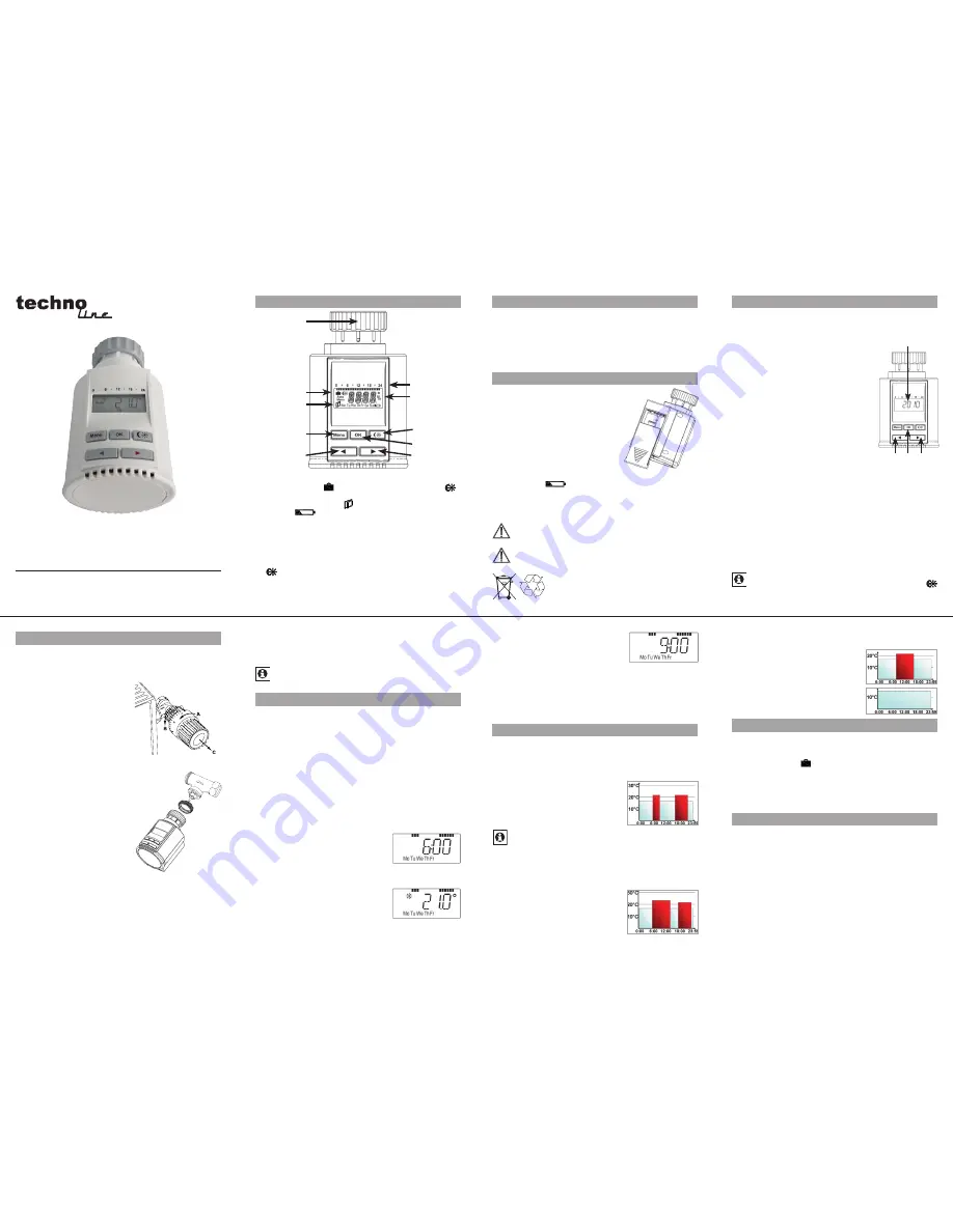
2. Weekly program: Examples
The energy-saving controller allows you to store up to 2 heating
periods (4 switching times) with individual temperature settings
for each day of the week. The factory setting consists of two
heating phases (from 6:00 until 9:00 and from 17:00 until 23:00
respectively) for every single day of the week:
From 00:00 to 06:00
17.0°C
From 06:00 to 09:00
21.0°C
From 09:00 to 17:00
17.0°C
From 17:00 to 23:00
21.0°C
From 23:00 to 23:59
17.0°C
The display shows bars for every heating interval. In this
example, no bars are shown for the interval from 0:00 to
6:00. Bars are only shown on the display for the intervals
from 6:00 to 9:00 and from 17:00 to 23:00.
If a room also needs to be heated at around noon, the corre-
sponding program might look like this:
Monday to Sunday
From 00:00 to 06:00
17.0°C
From 06:00 to 14:00
22.0°C
From 14:00 to 17:30
17.0°C
From 17:30 to 23:30
21.0°C
From 23:30 to 23:59
17.0°C
If you have a home office and only want it to be heated during the
day on working days, you can program the following times:
Monday to Friday
From 00:00 to 08:30
17.0°C
From 08:30 to 17:00
21.0°C
From 17:00 to 23:59
17.0°C
Saturday and Sunday
From 00:00 to 23:59
17.0°C
3. Operating modes
To switch between the 3 operating modes described below,
press the menu button briefly (these operating modes can only
be selected following installation/Step 3):
Holiday function
•
( )
:
Set a temperature that is to be main-
tained until a fixed point in time.
Manu:
•
Manual operation – The temperature is set manually
using the arrow buttons.
Auto:
•
Weekly program – The temperature is controlled auto-
matically in accordance with the stored weekly program.
4. Configuration menu
The configuration menu can be used to modify settings. To ac-
cess this menu, press and hold down the menu button (for more
than 3 seconds).
PRO: For setting the weekly program (see Section “1 Setting
•
the weekly program”)
DAT: For modifying the time of day and date
•
POS: For querying the actuator’s current position
•
DST: Automatic switchover at the start or end of daylight sav-
•
ing time can be deactivated.
AER: For setting the “window open” temperature and time
•
(the temperature is automatically reduced in the event of
ventilation)
TOF: For setting the offset temperature
•
Please read this manual carefully in order to help you put the
device into operation. Keep the manual handy so you can refer
to it at a later date!
A Thermal ring
B Holiday function ( ), set-back/comfort temperature (
),
manual operation (
Manu
), automatic operation (
Auto
)
C “Window open” symbol ( ), day of the week, “battery empty”
symbol (
)
D Menu button: Press and hold down the button for more than
3 seconds to open the configuration menu
E Colder/arrow button: Settings / temperature adjustments
F Switching periods set within weekly program
G Current temperature setting , time and date indicator, menu
items, functions
H
-button: For switching between set-back and comfort
temperatures
I OK button: For confirming/saving, teaching in
J Warmer/arrow button: Settings/temperature adjustments
5
2
6
3
7
4
8
TM3070-RF