© 2000 CONTRIVE • B1401|400.EN
0211
6
www.contrive.it
DUAL STAGE GAS BURNER
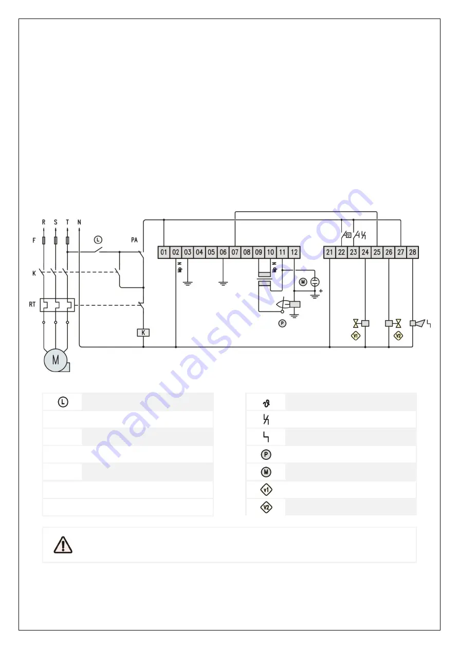
Contact output at terminal 25/26 can be used to manage a dual stage burner.
First stage intermittent gas valve is connected to terminal 24 (internally connected to terminal 25) and wired to
terminal 7 (gas valve output). This output is kept open once the flame signal is detected.
Second stage gas valve is connected to terminal 26 and powered 3 seconds after pilot burner successfully ignited.
Both valves are turned off when flame quenches or following any lockout or shutdown request.
In the following example the ignition and detection of the first stage is achieved by means of shared rod, an UV
detector could be installed on the 2
nd
stage of the burner. Both detectors are connected in parallel to same input.
Any lockout will turn on the alarm output at terminal 28.
Push the front panel button or close the reset input at terminal 23 to reset from lockout. The reset will take place
only when the button or contact are released.
Input at terminal 23 is meant for reset purpose only, no action is performed closing this input while burner is
running.
EXTERNAL LIMITS
THERMOSTAT
F
LINE FUSE
RESET INPUT
K
BLOWER POWER RELAY
BURNER LOCKOUT
RT
BLOWER THERMAL PROTECTION
PILOT SINGLE ROD
M
BLOWER MOTOR
MAIN UV SENSOR
PA
LOW AIR PRESSURE SWITCH
PILOT GAS VALVE
MAIN GAS VALVE
ALL SAFETY SWITCHES SHOULD BE APPROVED AS LIMIT CONTROLS
THE USE OF ELECTRONIC SWITCHES MAY CAUSE ERRATIC OPERATIONS


