Continental Hydraulics Installation Manual
Page 5 of 20
CEM-BPS-B
CHI 1020813 Jan 2016
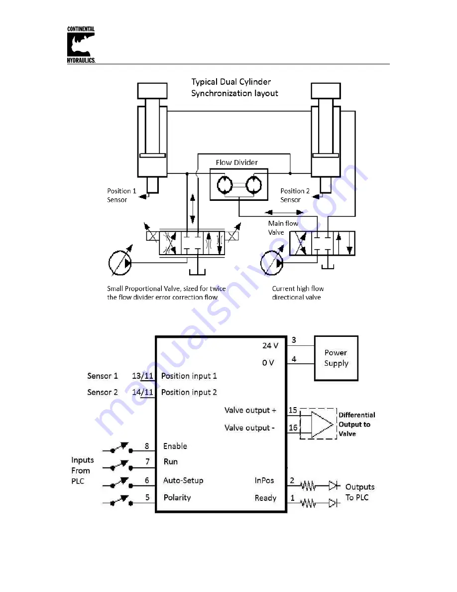
Typical Schematic Example:
Typical Wiring Example:
Страница 1: ...nd of synchronization control is extremely stable and simple to use With the AUTO SETUP input feature the offset error between both sensors can be measured and compensated automatically For this setup...
Страница 2: ...pply 6 Wiring 6 Terminal Identification 7 Steps to install and configure a new application 8 Commissioning 9 Parameter Overview 10 LED Indications 11 Command Parameter Descriptions LG Language 12 MODE...
Страница 3: ...um resolution 1 m Analogue outputs Voltage V 2 x 0 10 differential output mA 10 max load Signal resolution 0 006 Current mA 4 20 390 Ohm maximum load Signal resolution 0 006 Controller sample time ms...
Страница 4: ...Continental Hydraulics Installation Manual Page 4 of 20 CEM BPS B CHI 1020813 Jan 2016 Functional Diagram...
Страница 5: ...Continental Hydraulics Installation Manual Page 5 of 20 CEM BPS B CHI 1020813 Jan 2016 Typical Schematic Example Typical Wiring Example...
Страница 6: ...supply a star shaped ground wiring scheme is recommended The following points must be observed when wiring The signal cables must be laid separately from power cables Analogue signal cables must be s...
Страница 7: ...utputs Terminal 8 Enable input General enabling of outputs and the application Terminal 7 START RUN input ON The Synchronization controller is active OFF The Synchronization controller is not active A...
Страница 8: ...Microsoft Windows application 1 Mount the module in a suitable location 2 Connect the power supply and valve solenoids 3 Down load and open the GUI program www continentalhydraulics com wp content upl...
Страница 9: ...TINGS and DECELERATION Parameterize specific settings for the control element MIN for deadzone compensation and MAX for maximum velocity Pre parameterization is necessary to minimize the risk of uncon...
Страница 10: ...SIGNAL X1 U0 10 Type of input N_RANGE X1 100 mm Sensor nominal length OFFSET X1 0 m Sensor offset SIGNAL X2 U0 10 Type of input N_RANGE X2 100 mm Sensor nominal length OFFSET X2 0 m Sensor offset Clos...
Страница 11: ...rmal functions are possible 2 All LEDs flash shortly every 6 s An internal data error was detected and corrected automatically The module still works regularly To acknowledge the error the module has...
Страница 12: ...t influence on system behavior and should accordingly be changed with care SENS monitoring of the module functions Command Parameters Unit Group SENS x x ON OFF AUTO STD This command is used to activa...
Страница 13: ...active motion profile the output to the valve is ramped to zero INPOS Size of the control deviation window Command Parameters Unit Group INPOS x x 2 200000 m STD This parameter is entered in m The INP...
Страница 14: ...is available for all analog inputs X1 and X2 OFF Deactivation of the input N_RANGE X Nominal range of the sensor Command Parameter Unit Group N_RANGE i x i X1 X2 x 10 10000 mm EASY N_RANGE nominal ran...
Страница 15: ...mple the system is defined by a length of 120 mm of the sensor a working stroke of 100 mm of the cylinder and an offset of 5 mm These parameters have to be typed in and the axis is driving between 5 m...
Страница 16: ...istance must also be adjusted Otherwise this can result in instability and uncontrolled movements PT1 Timing of the controller Command Parameters Unit Group PT1 x x 0 300 ms EXP This parameter can be...
Страница 17: ...t can also lead to longer positioning times in individual cases LIN Linear deceleration characteristic gain is increased by a factor of 1 SQRT1 Root function for braking curve calculation The gain is...
Страница 18: ...justment is performed either at the power amplifier or in the module If the MIN value is set too high this has an effect on the minimum speed which can then no longer be adjusted In extreme cases this...
Страница 19: ...I4 12 20 U 10 I20 12 4 EXP This command is used to define the output signal voltage or current and to change the polarity4 Differential output 100 corresponds with 10 V 0 10 V at PIN 15 and PIN 16 Cu...
Страница 20: ...polarity can be changed with the POL command or by reversing the connections to PIN 15 and PIN 16 ENABLE and START are active the READY LED is on the STATUS LED is not on and a tracking error is not...