background image

3. Each Component Function


22

Hardware Manual

Specifications

[Input section]

-

Input specification

: Photocoupler-insulated current drive input

-

Input resistance

: 3k

-

Number of input signals

: 3

-

Input protection circuit

: Reverse-connection protection diode provided

-

Input response time

: Within 100

µ

sec

-

External circuit power supply

: 12 - 24VDC(±10%)

[Output section]

-

Output specification

: Photocoupler-insulated open-collector output

-

Output rating

: 30VDC, 100mA max.

-

No. of output signals

: 3

-

Output response time

: Within 300

µ

sec

Содержание IPC-PT/LS15 Series

Страница 1: ...IPC Series Panel PC with Windows CE NET 4 2 IPC PT MV15 Series IPC PT LS15 Series Hardware Manual CONTEC CO LTD...

Страница 2: ...ange without notice All relevant issues have been considered in the preparation of this document Should you notice an omission or any questionable item in this document please feel free to notify CONT...

Страница 3: ...VIEW 7 Specifications 7 External Dimensions 10 3 EACH COMPONENT FUNCTION 11 Component Locations 11 Serial Port Interface COM1 COM2 13 Switching COM2 between RS 232C and RS 422A 485 14 COM2 RS 422A RS...

Страница 4: ...mode setting DIP SW SW4 26 4 HARDWARE SETUP 27 Installation Requirements 27 Card removal prevention fitting 28 AC adapter code removal prevention fitting 28 Back light exchange 29 Attaching the Fitti...

Страница 5: ...iv Hardware Manual...

Страница 6: ...ut the need for a shutdown procedure Features LCD arm VESA compliant 75 mm type available for installation 128MB SDRAM system memory standard 32 MB of internal erasable programmable Flash ROM availabl...

Страница 7: ...when this device is returned freight prepaid with a copy of the original invoice and a Return Merchandise Authorization to the distributor or the CONTEC group office from which it was purchased This w...

Страница 8: ...ediately turn OFF the power to this device disconnect the plug from the power outlet and contact the manufacturer Continued use could lead to fire or electrical shock Because of the danger of electric...

Страница 9: ...o touch the touch panel Doing so may scratch the touch panel resulting in malfunctions Do not subject the touch panel to shock as doing so may break it When the surface or frame of the touch panel has...

Страница 10: ...NECON PC as a request for repair at an additional cost If installed horizontally with the LCD panel face up the unit should be used at an ambient operating temperature of not greater than 30 degrees c...

Страница 11: ...1 Introduction 6 Hardware Manual...

Страница 12: ...Settable for RS 422 485 LAN 10BASE T 100 BASE TX 1ch NS DP83816A PS 2 Keyboard I F PS 2 type 6 pin MINI DIN Capable of using both of keyboard and mouse with commercial PS 2 branch cable PC card slots...

Страница 13: ...e resistance Static electricity resistance Atmospheric discharge 8kV EN61000 4 2 Level 3 IEC1000 4 2 Level 3 Vibration resistance Anti shaking 10 50Hz semi amplitude 0 15mm One cycle 10 150 10 Hz of 1...

Страница 14: ...Vertical 0 50deg 65deg 90 40deg 60deg View angle Horizontal CR 10 90 Display Monochrome 40deg 60deg Contrast Display Monochrome 100 Brightness at center Display White 200cd m2 250cd m2 Contrast ratio...

Страница 15: ...ing length 4mm M3 TAP PCMCIA I O SPK RST USB UTP LNK KB COM2 COM1 ACT Figure 2 3 External Dimensions IPC PT MV15DC1 series IPC PT LS15DC1 series mm 308 276 130 4 5 242 130 216 F 1 F2 F 3 V V V V 1 2VD...

Страница 16: ...DC IN POWER LED Function switch F1 F2 F3 PCI expansion unit connector cover AC adapter jack 12VDC power connector ACT COM1 COM2 KB LNK UTP USB RST SPK I O PCMCIA Sound RESET KeyBoard COM2 COM1 USB UTP...

Страница 17: ...onnector AC adapter jack 12 VDC AC adapter jack PCI expansion unit connector cover Used to attach the PCI expansion unit and to set SW2 SW3 SW4 and JP5 PCMCIA PCMCIA card slot I O Insulated I O connec...

Страница 18: ...No Signal name Function Direction Signal name Function Direction 1 CD Carrier detection In GND Signal ground 2 RD Received data In RTS Request send Out 3 TD Transmitted data Out RTS Request send Out 4...

Страница 19: ...setting Factory setting 1 12 B C A RS 422A 485 setting 1 12 B C A Figure 3 2 Setting procedure JP5 Table 3 4 Settings for RS 232C and RS 422A 485 RS 232C Factory setting RS 422A 485 Setting procedure...

Страница 20: ...1 2 3 4 5 6 7 8 ON Description Only TxD is enabled as a data line The transmission or reception mode can be selected by the RTS signal from this product If the connected device has no RTS and CTS sign...

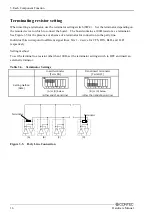
Страница 21: ...e party line Individual bits correspond to different signal lines bits 1 4 serve for CTS RTS RxD and TxD respectively Setting method To set the terminal to a resistor other than 100 set the terminator...

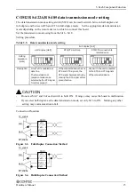
Страница 22: ...circuits for the data transmission mode setting and terminator setting switches SOUT SIN CTS RTS DCD DTR DSR RI SW4 1 8 TxD TxD RxD RxD CTS CTS RTS RTS Terminator 1 2W 100 6 2k 47k Vcc 6 2k 6 2k 47k V...

Страница 23: ...8 Signal name TX TX RX N C N C RX N C N C Remarks Transmitted data output Transmitted data output Received data input Not connected Not connected Received data input Not connected Not connected 8 1 AC...

Страница 24: ...DIN 6 pin Pin No 1 2 3 4 5 6 Remarks With fuse max 1 6A Signal name KBD DATA MOUSE DATA GND Vcc 5V KBD CLK MOUSE CLK 6 4 2 1 3 5 Note A commercially available PS 2 branch cable is required to use a P...

Страница 25: ...A type III card should be inserted into slot 2 Attaching the card removal prevention fitting PCMCIA Card Figure 3 8 Attaching the card removal prevention fitting Power Supply to the Card The voltage...

Страница 26: ...ports Table 3 11 General purpose I O ports connector 1 10 Front LCD side Pin No Signal name Remarks 1 PI_PCOM General purpose input plus common 2 PI 0 General purpose Input 0 3 PI 1 General purpose I...

Страница 27: ...nce 3k Number of input signals 3 Input protection circuit Reverse connection protection diode provided Input response time Within 100 sec External circuit power supply 12 24VDC 10 Output section Outpu...

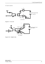
Страница 28: ...ion 3k 1 2 External power supply 12V 24VDC Input contact PI_PCOM PI 0 PI 2 I O connector 10k Figure 3 9 In circuit P_PO 0 P_PO 2 N_PO 0 N_PO 2 External power supply Max 30VDC External circuit I O conn...

Страница 29: ...r connector Table 3 12 Dedicated power input connector 1 4 Pin No Signal name 1 GND 2 GND 3 12VDC 4 12VDC Table 3 13 AC adapter jack 1 2 Pin No Signal name 1 12VDC 2 GND CAUTION All the terminals are...

Страница 30: ...ouch panel specifications Model IPC PT MV15DC1 4E IPC PT LS15DC 4E Detection method Analog resistive Active area 211 2 x 158 4mm 246 x 184 5mm Surface treatment No glare Resolution 4096 x 4096 emulate...

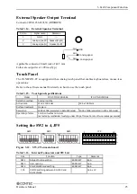
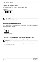
Страница 31: ...switch available for use by the application Refer to the software manual for details on how to use this DIP switch 1 2 3 4 ON Default setting Default setting of DIP switch Figure 3 14 General Switch C...

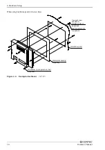
Страница 32: ...hin the installation environment requirement range provide a gap of 30mm or more between the main unit and any adjacent equipment Side view Panel 30mm or more above 30mm or more Bottom 30mm or more ba...

Страница 33: ...ting into the long slot on the PANECON PC unit 3 Use a screw to attach the top of the fitting PCMCIA Card Figure 4 2 Attaching the card removal prevention fitting AC adapter code removal prevention fi...

Страница 34: ...fe When it expires and requires replacement contact your local CONTEC sales office Attaching the Fitting Used to Attach to the Main Unit When installing on a STUD installation panel supplied M3 Washer...

Страница 35: ...sing installation panel with screw holes Tree point screw and washer assembly 6 M3x20 Sealing washer 6 M3 Installation panel supplied M3 Washer Spring washer Nut Waterproof packing supplied supplied s...

Страница 36: ...ess 130 0 3 216 0 3 164 0 3 224 0 3 mm Figure 4 5 Panel cut dimensions figure IPC PT MV15DC1 4E 308 0 3 130 0 3 252 0 3 8 M3 STUD 4 R1 or less 190 0 3 92 0 3 130 0 3 242 0 3 Or 6 4 mm Figure 4 6 Panel...

Страница 37: ...unit connector cover The PCI expansion unit connector cover on the back must be removed when you install the PCI expansion unit or set SW2 SW4 and JP5 1 Undo the 2 flat head screws and remove the cov...

Страница 38: ...put 100 240 VAC Below 1 3 A Input voltage 100 VAC Output 12 VDC 3 5 A PCI expansion unit IPC PAC PCI C1 1 slot expansion unit for PCI half size Manual IPC PT 15SH4 HMJ Hardware manual Japanese for IPC...

Страница 39: ...shiyodogawa ku Osaka 555 0025 Japan Japanese http www contec co jp English http www contec com Chinese http www contec com cn No part of this document may be copied or reproduced in any form by any me...

Отзывы: