Contec IPC-DT/H40X(PC)T Скачать руководство пользователя страница 6

1. Introduction


User’s Manual

3

Handling Precautions

Take the following precautions when handling this board.

- This display is made of the precise electric parts, so do not use or

store it in the vicinity of impulse or vibration.

- Do not use or store the product in a location exposed to extremely

high or low temperature or susceptible to rapid temperature
changes.
Example:

- Exposure to direct sun
- In the vicinity of a heat source

- There are switches and jumpers on the board that need to be set in

advance.    Be sure to check these before installing to the
expansion slot.    Only set the switches and jumpers on the board
to the specified settings.    Otherwise, the product may cause a
failure.

- Do not use the product in extremely humid or dusty locations.

- This product is not intended for use in aerospace, space, nuclear

power, medical equipment, or other applications that require a
very high level of reliability.    Do not use the product in such
applications.

- If you utilize this product in such usages where high reliability

and safety are required as on the trains, vessels, automotives or
crime- or disaster-prevention devices, contact your retailer.

- Do not use touch panel key operations to initiate actions where

there is a risk of loss of life or serious injury.    Ensure that the
system design can handle the case when a key is pressed by
mistake.

- Do not use any sharp-pointed object such as a mechanical pencil

to touch the touch panel.    Doing so may scratch the touch panel,
resulting in malfunctions.

- Do not subject the touch panel to shock as doing so may break it.

- Do not modify the product.    CONTEC will bear no

responsibility for any problems, etc., resulting from modifying
this product.

- Use the power supply intended for use with this unit whenever

possible.    If using a power supply other than the intended power
supply, ensure that it satisfies the required voltage and maximum
current ratings.

- Never disconnect the display cable when the host computer is

turned on.    To avoid damage to the display, turn off the computer
before inserting or disconnecting the display cable.

- In the event of failure or abnormality, contact your retailer.

Содержание IPC-DT/H40X(PC)T

Страница 1: ...IPC Series FLAT PANEL DISPLAY For PanelLink IPC DT L40S PC T IPC DT H40X PC T User s Manual CONTEC CO LTD...

Страница 2: ...ithout notice All relevant issues have been considered in the preparation of this document Should you notice an omission or any questionable item in this document please feel free to notify CONTEC CO...

Страница 3: ...Optical Display Specifications 9 3 Outside Dimensions and Part Names 11 Outside Dimensions 11 Part Names 14 4 Setting the Display 15 Setting the DIP switch 15 Specifications of Remote Control Cable C...

Страница 4: ...tyle keyboard less operation Panel Link Interface allowing a cable of up to 5 m in length to be used Thin panel unit has a mounting depth of only 38mm when input directly to 5VDC terminal Back mounted...

Страница 5: ...the device has been tampered with or damaged through abuse mistreatment neglect or unreasonable use or if the original invoice is not included in which case repairs will be considered beyond the warra...

Страница 6: ...this product in such usages where high reliability and safety are required as on the trains vessels automotives or crime or disaster prevention devices contact your retailer Do not use touch panel ke...

Страница 7: ...gular maintenance is necessary for the backlight on the touch panel and the display for the longevity parts Burn in on TFT Display Burn in may occur if the same display is retained for a long time Avo...

Страница 8: ...ipment is operated in commercial environment This equipment generates uses and can radiate radio frequency energy and if not installed and used in accordance with the instruction manual may cause harm...

Страница 9: ...1 Introduction 6 User s Manual...

Страница 10: ...terface used 1 Power supply interface 4 pin nylon connector for 5 VDC power supply Input at 85 to 264 VAC is enabled by using the back mounted optional power supply unit IPC POA100D Resolution 4096 x...

Страница 11: ...Power supply IPC POA100D Sweep durability 10 50 Hz Single side amplitude or 0 15 mm 50 500 Hz 2 0 G in the X Y Z directions for 23 minutes each Conforming to JIS C0040 and IEC68 2 6 Vibration resistan...

Страница 12: ...nter 1 Display in white 350cd m2 Typ 250cd m2 Typ 1 Surface brightness is a numerical value in a display simple substance The brightness that let the touch panel pass serves as about 77 of the above m...

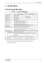
Страница 13: ...2 Specifications 10 User s Manual...

Страница 14: ...100 279 98 98 98 100 mm Figure 3 1 Outside Dimensions of Main Unit IPC DT L40S PC T IPC DT H40X PC T 4 M4 TAP Including the mate Maximum tapping length 4mm 4 M4 TAP Maximum tapping length 4mm 4 M4 TAP...

Страница 15: ...98 119 119 119 280 140 48 5 85 17 12 M4 STUD 2 4 38 13 58 67 mm Figure 3 3 Dimensions of IPC DT L40S PC T with IPC POA100D IPC DT H40X PC T with IPC POA100D power supply unit 2 4 38 13 58 67 428 336 1...

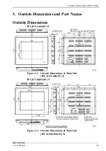
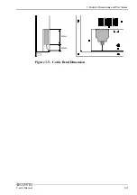
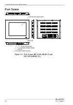
Страница 16: ...3 Outside Dimensions and Part Names User s Manual 13 45mm 20mm Figure 3 5 Cable Bend Dimension...

Страница 17: ...rt Names 14 User s Manual Part Names Touch panel over liquid crystals Power LED Panel Link connector 5VDC power supply connecotr DIP SW Remoto control cable connector Figure 3 6 Part Names IPC DT L40S...

Страница 18: ...le the display built in buzzer to sound upon a touch on the touch panel The buzzer ON OFF setting can also be controlled by driver software 1 ON Disable the display built in buzzer from sounding upon...

Страница 19: ...ND Brightness DOWN Backlight ON OFF 1 GND GND Cable connector Side type S6B XH A LF SN mfd by JST Connector type Model 1 2 3 4 5 6 1 2 3 4 5 6 Connector application example 1 2 3 4 5 6 SW1 SW2 SW3 Pus...

Страница 20: ...he display The four corners of the solid line rectangle define the panel cut dimensions The holes 12 on dashed lines represent stud holes 119 119 119 344 98 98 98 281 12 05 mm Figure 5 1 Display Mount...

Страница 21: ...User s Manual 2 Insert the supplied gasket between the panel and the display then fasten them together with M4 nuts as shown below Display Gasket Panel Figure 5 3 Assembling Method Note The panel must...

Страница 22: ...to be connected must be set up correctly for using the display Set the IPC DT L40S PC T to SVGA 800 x 600 or the IPC DT H40X PC T to XGA 1024 x 768 Set the LCD type as follows depending on the host c...

Страница 23: ...Chapter 4 Note Use this board along with the 26 20 pin conversion cable IPC PL2620 002 C PC 686E PC LV To use this SBC board with the display set the on board rotary switch as shown below Table 6 1 PC...

Страница 24: ...2 S2 Switch Settings Note Use this board along with the LCD signal conversion mini board EXLCD68 and the ISA bus type of LCD signal conversion board ADPLNK PC PC 586HU PC LV To use this SBC board with...

Страница 25: ...s box computer with the display set the on board switch S1 as shown below 12 1 inch IPC DT L40S PC T 15 inch IPC DT H40X PC T Set 6 7 and 8 to ON TFT color LCD in 800 x 600 TFT color LCD in 1024 x 768...

Страница 26: ...ction Example Illustrated below is an example of connecting the display to the box computer IPC BX M600 PCW C CP Panel Link cable Option IPC PL2020 020 2m IPC PL2020 050 5m Display IPC DT L40S PC T IP...

Страница 27: ...Rise time to 4 75V Figure 6 6 Power On Sequence Table 6 2 Power Supply Connector Connector type Model 5VDC input connector B4PS VH LF SN mfd by JST Pin No 1 2 3 4 Signal name GND GND 5V 5V Applicable...

Страница 28: ...the Panel Link connector on the back of the display Table 6 3 Panel Link Connector Connector type Model Panel Link Interface connector CN3 N10220 5DG3 PL mfd by 3M Pin No A1 A2 A3 A4 A5 A6 A7 A8 A9 A...

Страница 29: ...6 Connection to the Host Computer and Power Supply 26 User s Manual...

Страница 30: ...ch panel controller and passed to the host PC via the serial port on the CPU in the controller Before the touch panel can be used touch panel driver software TPBK PC S must be installed Note that the...

Страница 31: ...7 Touch Panel 28 User s Manual...

Страница 32: ...IB 01 Driver Utility Soft Set CD ROM version Power unit IPC POA100D 100V to 240VAC power unit IPC POD24 5 24VDC input power unit LCD I F board ADPLNK PC H Panel Link I F board for SBC ISA bus Optional...

Страница 33: ...yodogawa ku Osaka 555 0025 Japan Japanese http www contec co jp English http www contec com Chinese http www contec com cn No part of this document may be copied or reproduced in any form by any means...

Отзывы: