11
3.
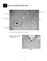
Remove Lock Pins from
square adapter and slide over
Mounting Tube on Power
Unit. Reinstall Lock Pins.
(See Figure 2)
Figure 2
4.
Slide Sheave Extension into
Square Adapter. Reinstall
Lock Pin. (See Figure 3).
Sheave Extension can be
adjusted to desired height
during puller set-up.
Figure 3
5.
Remove Hitch Pin from
Extension Head Bracket and
slide Fork over Sheave
Bracket and replace Hitch Pin
(See Figure 4)
Figure 4
6.
Puller is completely assembled.
Содержание CableGlider LW
Страница 1: ...USER S GUIDE SAFETY MANUAL CableGlider LW Cable Puller...
Страница 2: ...2...
Страница 14: ...14 Appendices LW CableGlider Assembly 5...
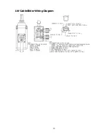
Страница 16: ...16 LW CableGlider Wiring Diagram...
Страница 19: ...19 NOTES...
Страница 20: ...20 NOTES...
Страница 21: ...21 NOTES...


