12
S 4
Installing the S module
Follow the procedure below if the S module is not fitted on delivery.
Remove the front cover.
Switch off the batteries.
Disconnect the mains power supply.
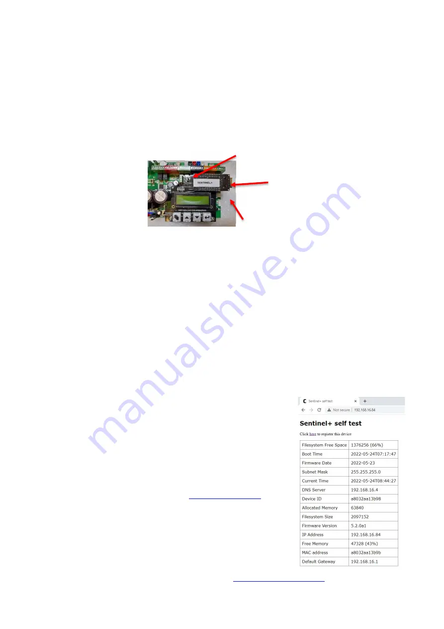
Fit the S module to the female header sockets on the LCD PCB in the position shown below ensuring
that the pins locate correctly, i.e., the pins line up starting from the left.
Connect ethernet cable.
Switch on the batteries and reconnect the mains power supply.
NB: Installing a S module with power applied to the Smoke Screen may cause the LCD
display to corrupt – pressing the Function menu button should return the display to normal
operation.
Setting up the S
See Section 6.10 for information on programming and then make the following entries as required:
By default, the S IP address is set to 0.0.0.0 – This will use DHCP to attempt register onto the network,
if successful the assigned IP address for the unit will be visible under the ‘Telemetry’ setting of LCD display menu.
If a static IP is required, you must manually enter IP address and
subnet mask. You may also need to configure a default gateway
address and a DNS server address. If you are unsure what
settings to use then contact your Network Administrator.
NOTE: When making changes to the network settings, once all
values have been entered - enter the ‘Send Special Command Codes’
menu select ‘Send Command 1’ then ‘Enter’
In a browser enter the IP address, for example:
http://192.168.16.84/
The S test page will be shown on the browser.
The S can now be registered for online monitoring. See Section 7.3
The Sentinel can now be remotely programmed if required. See Section 6.11
A simplified device monitoring page is available, for example:
http://192.168.16.84/status
Ethernet cable socket.
Note the Ethernet port overhangs the
side of the LCD PCB.
Содержание Sentinel S100
Страница 1: ...SENTINEL S70 S100 S150 v7 v1 2 INSTALLATION AND OPERATION MANUAL Revised Version July 2022 ...
Страница 14: ...13 Connections 5 5 1 CIRCUIT BOARD LAYOUT ...
Страница 15: ...14 5 2 CONNECTION DIAGRAM USING SMOKE SCREEN INTERFACE Recommended ...
Страница 16: ...15 5 3 CONNECTION DIAGRAM GENERIC ...
Страница 35: ...34 Installer Notes ...


