background image

MULTIPLEXER CONTROLLING 

TP4MD/CD / TP10MS/MD/CD / TP16MS/MD/C


E

N

G

L

IS

H


1. 1-16 

Press  the  buttons  1 - 16  to  display  the correspon-
ding camera image. 

2.


REC 

Press  the  button  REC  to  start  recording  to  the 
VCR. 

3.


HOLD


Press  the  button  HOLD  to  freeze  all  cameras  on 
the divided screen. 

4. PLAY 

Press  the  button  PLAY  to  start  the playback from 
the VCR. 

5. SEQ  

Press the button SEQ to control an analogue chan-
nel MON SPOT. 

6. MENU 

Press  the  button  MENU  to  display  the  on-screen 
menu. 

7. DIRECTION ARROWS 

These  buttons  are  used  for  moving  in  the  menu 
and  for  controlling  the  pan/tilt  camera  heads  and 
zoom lenses in telemetry. 

8. ZOOM +/- 

By  pressing  the  buttons  ZOOM  it  is  possible  to 
control the digital zoom (PLAY mode only) and the 
optical zoom for telemetry. 

9. FOCUS +/- 

Focus controlling buttons for telemetry 

10. IRIS +/- 

Iris controlling buttons for telemetry 

11. VIEW 

After pressing the button VIEW it is possible to se-
lect  various  types  of  displaying  of  the  camera 
numbers on the screen. 

12. MACRO 

Press the button MACRO to load the defined mac-
ros.  


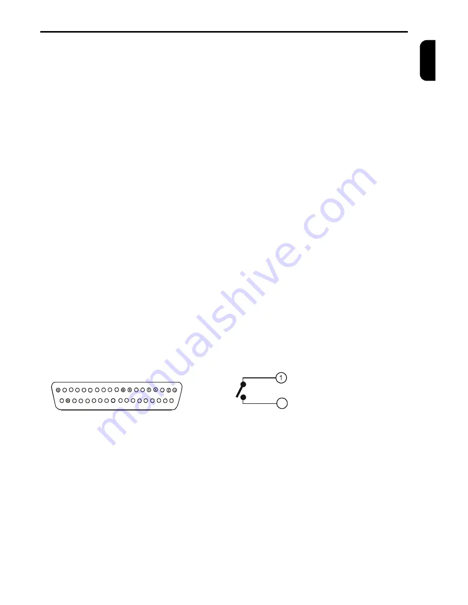
Fig. 3a: D-SUB37M alarm connector 

18

17 16

15

14

13

12

11

10

7

6

3

20

21

22

23

24

25

26

27

28

29

30

31

32

33

34

35

37


13. ALARM 

      Press the button ALARM to display the alarm 
      status. Press the button again to display the list of  

 alarm events.  

14.AUTO  
     

Press the button AUTO to starts/stop the auto  

     matic camera switching, according to the pro- 
     grammed sequence. 

15. PRESET 

By  pressing  the  button  PRESET  it  is  possible  to 
set up prepositions of the connected devices. This 
button has more telemetry functions. 

16. IN1 – IN16 

Video inputs for cameras 1 – 16. 
The video inputs are automatically terminated if the 
corresponding video output is left unconnected. If a 
device is connected to video out make sure that it 
is properly terminated.  

17. VCR IN 

Use this video input for connecting from VCR. 

18. SPOT 

Video output to spot monitor. 

19. OUT1 – OUT16 

Video outputs for cameras 1 – 16.  

20. VCR OUT 

Video output to VCR. 

21. MAIN 

Video output to main monitor. 

22. MAIN 

S-VHS video output to main monitor ( only for col-
our multiplexers ). 

23.ALARM 

Connector serve for RS 485, RS 232 and CAN in-
terfaces  and  enables  connecting  alarm  contact 
makers, sensors, ect.  

24. DC12V 

Connector  for  connecting  power  supply 

(12VDC, 

min 700mA)


Fig. 3b: Alarm output internal connection 


Contact 1

20

Contact 2


  (1) 

Alarm output – contact 1


  (2) 

Reserve


  (3) 

Common input conductor – ground (GND)


  (4) 

Alarm input 1


  (5) 

Alarm input 3


  (6) 

Alarm input 5 (TP10, TP16)


  (7)

 Alarm input 7 (TP10, TP16)


  (8)

 Alarm input 9 (TP10, TP16)


  (9) 

Alarm input 11 (TP16)


(10) 

Alarm input 13 (TP16)


(11) 

Alarm input 15 (TP16)


(12) 

Common input conductor – ground (GND)


(13) 

RS 232 RX


(14) 

RS 232 TX


(15)

 CAN terminating resistance


(16) 

CAN_L, connect to twist pair cable conductor


(17) 

Common input conductor – ground (GND)


(18)

 RS 485 A (+)


(19) 

RS 485 terminating to use connect with (18) 


(20)

 Alarm output – contact 2


(21) 

Common input conductor – ground (GND)


(22) 

AUX input from VCR


(23)

 Alarm input 2


(24)

 Alarm input 4


(25) 

Alarm input 6 (TP10, TP16)


(26) 

Alarm input 8 (TP10, TP16)


(27) 

Alarm input 10 (TP10, TP16)


(28) 

Alarm input 12 (TP16)


(29) 

Alarm input 14 (TP16)


(30) 

Alarm input 16 (TP16)


(31)

 Common input conductor – ground (GND)


(32)

 RS 232 RTS 

(33)

 RS 232 CTS 

(34)

 CAN_GND, connect to shielding of the cable 

(35)

 CAN_H. connect to twist pair cable conductor 

(36)

 RS 485 B (-) 

(37)

 CAV_V+, (5V/100mA) – do not connect


Содержание TP10CD

Страница 1: ...ENGLISH BLACK WHITE AND COLOUR MULTIPLEXERS Installation and user manual TP4MD TP10MD TP16MD TP4CD TP10CD TP16CD ...

Страница 2: ......

Страница 3: ...CAN RS 485 RS 232 INTERFACE 4 EXTERNAL KEYBOARD 4 MULTIPLEXER NETWORKING 4 MULTIPLEXER CONTROLLING 5 CAMERA DISPLAYING LIVE 5 PLAYBACK PLAY 5 DIGITAL ZOOM ZOOM 5 PICTURE RECORDING REC 5 ANALOGUE CHANNEL CONTROLL SEQ 5 DISPLAYING VCR INPUT VCR 5 SELECT VIEW VIEW 5 TELEMETRY CONTROLLING 5 FREEZE PICTURE HOLD 6 LOAD MACRO MACRO 6 ALARM STATUS ALARM 6 LIST OF EVENTS 6 MENU 7 MAIN MENU 7 VIDEORECORDER ...

Страница 4: ...tching The spot channel is used even for manual controlling from the main panel o 4 10 or 16 video inputs o main and spot output o VCR input and output o automatic TV standard detection from connected cameras o 864 samples per a TV line CCIR PAL 856 EIA NTSC o 576 active TV lines CCIR PAL 480 EIA NTSC o 256 grey scale 16 million colours o RS 485 and CAN interface for telemetry control ling of pan ...

Страница 5: ...tions 16 IN1 IN16 Video inputs for cameras 1 16 The video inputs are automatically terminated if the corresponding video output is left unconnected If a device is connected to video out make sure that it is properly terminated 17 VCR IN Use this video input for connecting from VCR 18 SPOT Video output to spot monitor 19 OUT1 OUT16 Video outputs for cameras 1 16 20 VCR OUT Video output to VCR 21 MA...

Страница 6: ...cted to the CAN bus You can connect several external keyboards to CAN bus and control different or the same devices During controlling of one device by several keyboards you are able to operate controlled device by another key board five seconds after the last command of the pre vious keyboard it is not possible to control one device from two keyboards at the same time MULTIPLEXERS NETWORKING Usin...

Страница 7: ... channel is switched on by pressing the button SEQ The buttons 1 to 16 are used for displaying a corresponding camera by press ing the button AUTO it is switched the automatic switching sequence on or off Set up sequential switching parameters using the menu Sequence Cameras in sequence and Time multiplier see page 8 and 9 By another pressing the button SEQ the mul tiplexer switches back into the ...

Страница 8: ...er leaving the cameras menu and pressing the PRESET button you return back to the pan tilt and lens controlling mode After that the PRESET disa pears from the status line FREEZE PICTURE HOLD During LIVE and PLAY modes pressing the button HOLD freezes the main channel monitor view The picture starts to move again by other pressing of this LOAD MACRO MACRO TP multiplexers enable to define so called ...

Страница 9: ...nction it is important to ensure that the VCR and multiplexer work in the same mode You can also define the type of the con nection between the VCR and the multiplexer with the help of AUX input VCR TYPE Set up your VCR type here If your VCR type is not mentioned here use an analogous type or choose a user defined VCR and set up the working VCR modes in the menu User defined VCR see page 7 VCR MOD...

Страница 10: ...CR and the multiplexer If the operator switches the recording speed on the VCR or the recording speed is changed by the influence of the alarm signal on the VCR the multiplexer changes its recording speed automatically Start record if the AUX input activity is detected multiplexer starts the recording automatically MENU CAMERA Set up camera parameters of recording displaying activity detection seq...

Страница 11: ...rameter TIME MULTIPLIER The time of the displaying of particular cameras can be quite lengthened or shortened and the proportion of displaying particular steps cameras still lasts It is important to note that the time of displaying one step after the change will still stay in interval of 1 to 255 seconds There is an illustrated example in the table how the switching time changes according to the p...

Страница 12: ...m inputs marking the line the alarm inputs will influence recording Activity detector if you mark this line the activity detector will influence recording Alarmed cameras only only the cameras with the alarm detection will be recorded during the alarm las ting The source of the alarm can be either from the alarm inputs or from the activity detector Selected alarmed cameras only only the cameras wi...

Страница 13: ...functions below than have no meaning No reaction to alarm no reaction to alarm inputs Follow input active during the alarm lasting on any of the inputs Switch on XX seconds active for the time from 1 to 99 seconds since the last alarm activation No reaction to camera fail no reaction to the video signal lost Switch on XX seconds active for the time from 1 to 99 seconds since the camera signal fail...

Страница 14: ...ctor will explore the image changes can be defined with the help of this matrix 18 x 9 of light sensitivity elements for every camera The transparent squares represent active fields There are described controlling buttons for editing the light sensitivity matrix here 1 sets one active matrix field 2 clears one field 3 sets the whole line 4 clears the whole line WALK TEST The walk test is used for ...

Страница 15: ...ded cameras will be changed after the macro is launched Select cameras by opening this submenu you can choose your own set of the cameras for recording Activity detector by marking this line the cameras for activity detection will be changed after the macro is launched Select cameras your own set of the cameras for activity detection Sensitivity of the detector by marking this line the sensitivity...

Страница 16: ...ist of events which corresponds to previous setting in this menu CLEAR LIST You can clear the list of events in this menu by pres sing the button 1 MENU SYSTEM In this menu you can set up such parameters which correspond to the functions of multiplexers as the password the data and time setting interlace correc tion telemetry characteristics and the language choice PASSWORD The user can control th...

Страница 17: ... the multiplexer and its format of displaying on the monitor If you choose some time and date item time will stop and will not start since this menu is finished TIME CORRECTION You can correct the multiplexer internal clock devia tions by setting the value of seconds added or taken off per a day For example If the clock of multiplexers delays 2 5 seconds a day increase the value of the correction ...

Страница 18: ...ess can be set up here Parameters setup parameters for selected protocol The following menus control the function of user out puts AUX1 AUX2 see Telemetry controlling on page 8 Change output by pressing one of the buttons AUX1 2 the state of user output will be changed Follow key The user output is switched on while holding the button AUX ENABLE EXTERNAL KEYBOARD marking this line you enable multi...

Страница 19: ...mination at the end of the line by the connected device or must be left unconnected Cameras on divided screen are slightly shaking Interlace correction is switched off oSet up the interlace correction of live picture in menu SYSTEM DISPLAY page 16 The shaking stops with result of slower displaying At colour multiplexer displayed have incorrect colours Improper setting of camera parameters oCheck t...

Страница 20: ...of the alarm inputs is defective oCheck the connection of the alarm inputs page 3 The device reacts to alarm inputs incorrectly The set up of alarm inputs polarity is incorrect oCheck the polarity of alarm inputs in menu ALARM INPUTS page 10 The alarm output relay does not react properly The polarity of alarm is set up incorrectly oSet up the normal state of alarm output in menu RELAY CONTACTS pag...

Страница 21: ...pin female connector AUX INPUT Loop connection input ground GND Activity programmable Maximum alarm loop impedance 1 kW ALARM OUTPUT Number 1 potentialless contacts of low voltage relay Maximum switching voltage 40 V Maximum switching current 0 5 A RS 485 INTERFACE Baud rate depend on protocol Maximum length 1000 m Terminators 120 W at both ends CAN INTERFACE Baud rate 50 kBs Maximum length bus st...

Отзывы: