Rev.01 03-27-17
Page 1 of 71
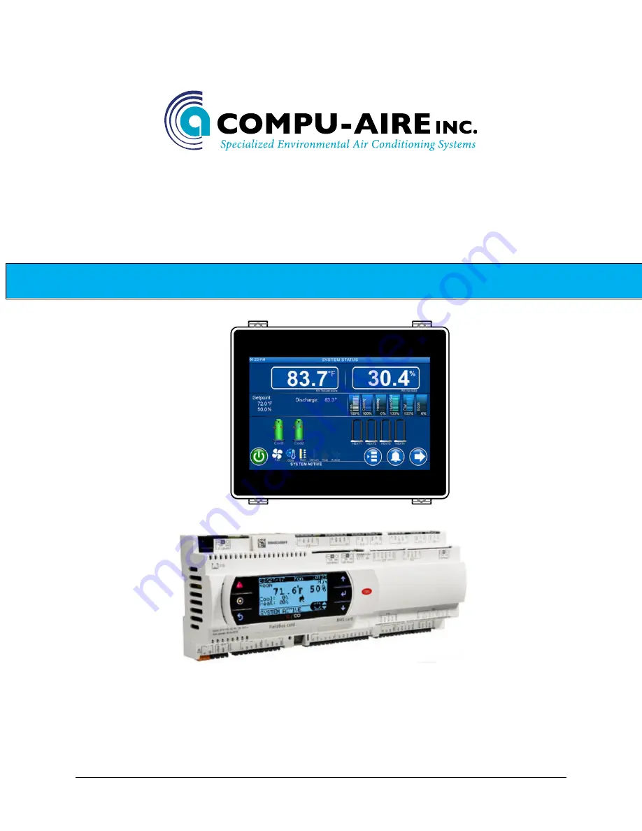
Compu-Aire
SYSTEM 2500
PROGRAMMABLE CONTROLLER
-USER MANUAL-
8167 Byron Road Whittier, CA 90606
Phone: (562) 945-8971 Fax: (562) 696-0724
SUBJECT TO CHANGE WITHOUT INCURRING OBLIGATION
Страница 1: ...v 01 03 27 17 Page 1 of 71 Compu Aire SYSTEM 2500 PROGRAMMABLE CONTROLLER USER MANUAL 8167 Byron Road Whittier CA 90606 Phone 562 945 8971 Fax 562 696 0724 SUBJECT TO CHANGE WITHOUT INCURRING OBLIGATI...
Страница 2: ...Cooled Energy Miser 15 3 8 Dry Fluid Cooler with Energy Miser 17 3 9 Special Pump and Dry Fluid Cooler control logic 19 3 10 Optional features 20 4 0 CONFIGURATION 20 4 1 Software version 20 5 0 TECHN...
Страница 3: ...1 Modbus 51 8 1 1 Mounting 51 8 2 LONWORKS 53 8 2 1 General characteristics 53 8 2 2 Physical channels 53 8 2 3 Physical Circuit Board Layout 53 8 2 4 LED Color Description 54 8 2 5 Installation 54 8...
Страница 4: ...9 SNMP 61 8 3 10 BACNET 61 8 3 11 WARNINGS 62 8 4 BANET over MS TP For BMS Card add on 63 8 4 1 Installation 63 8 4 2 Meaning of the jumpers 64 8 4 3 Operation 64 8 4 4 Recalling the factory configura...
Страница 5: ...17 Sensor calibration 34 Figure 18 Display setup 35 Figure 19 Manual controls 35 Figure 20 Network p LAN menu 36 Figure 21 IP address 37 Figure 22 Rotation schedules 37 Figure 23 Network configuratio...
Страница 6: ...e and time 49 Figure 45 Night setback 50 Figure 46 Building management system 50 Figure 47 Communication protocol 50 Figure 48 LONTalk Card 53 Figure 49 Remove plastic cover 55 Figure 50 Cut out windo...
Страница 7: ...ith built in navigation keypad and LED indicators allowing the users to easily set the controlled parameters for setpoints dead bands alarm thresholds and carry out the main working operations on off...
Страница 8: ...re configured per system configuration Further modification may be required to better fit the application Figure 1 User Interface 1 Power Link LED Solid green Normal operation Flashing green loss comm...
Страница 9: ...mpressor stage Active Green OFF Black Heating stage Active Red OFF Black Demand output Pumpdown mode Evaporator fan Humidifier mode Cooling mode Dehumidification mode Heating mode Econ cooling assist...
Страница 10: ...and relative humidity 2 Room return temperature and humidity setpoints 3 Cooling stages 4 Mode of operation 5 System ON OFF control 6 System demands outputs 7 Heating stages 8 Navigation system Main m...
Страница 11: ...afe operation For example when compressor failure occurs the failed compressor shall be locked out but the system shall provide cooling by other compressor if available On a heater failure the heaters...
Страница 12: ...to work independent of each other The Chilled Water System comes standard with a three 3 way water modulating valve coil and an optional no water flow switch The DX system is equipped with a DX coil c...
Страница 13: ...e If chilled water supply temperature is selected for switch over than the unit shall continue with chilled water cooling if the chilled water supply temperature is below the required temperature setp...
Страница 14: ...temperature When outdoor air is not suitable for economizer cooling the Economizer shall be locked out and the outdoor air damper shall maintain minimum position while the indoor fan is operating Upo...
Страница 15: ...em at 45 deg F entering water temperature The indoor unit will send a signal to enable and disable the outdoor auxiliary equipment The outdoor equipment has its own control logic to provide water temp...
Страница 16: ...of flow to auxiliary energy miser cooling coils and maintain constant temperature and relative humidity Energy miser systems are connected to Cooling Tower or Dry Fluid Coolers to obtain re circulatin...
Страница 17: ...l control box The Dry Fluid Cooler shall be arranged for Vertical Air Flow The Glycol Coil shall have aluminum fins bonded to copper tubes and shall have full collars that completely cover the copper...
Страница 18: ...below 50Deg F the aqua stat 1 will close and DFC unit will switch over to free cooling energy miser mode In Energy Miser mode all other aqua stats aqua stat 2 3 and 4 will be bypassed and all fans wil...
Страница 19: ...tly to allow pump minimum operating speed to be maintained should zone loads decrease thus decreasing flow below safe pump operation Outside air temperature reaches 48 deg F Pump controls switch to fr...
Страница 20: ...mmand computer or to an existing building automation system The System 2500 is truly one of the most powerful and flexible controllers available for HVAC units today 4 0 CONFIGURATION The display unit...
Страница 21: ...e created to customer request The controller runs the control program and is fitted with the set of terminals required for connection to the devices compressors fans etc The program and the parameters...
Страница 22: ...h screen interface 5 3 Mechanical Characteristics SMALL 13 DIN modules 110 x 227 5 x 60mm Plastic container Assembly Fitted on DIN rail as per DIN 43880 and IEC EN 50022 Material techno polymer Flame...
Страница 23: ...vices alarms device status indicators and remote switches Digital inputs are not optically isolated and have voltage free connects Figure 6 Digital inputs Note Separate the probe and digital input sig...
Страница 24: ...0mA voltage inputs dry contact or PWM The maximum number of analog inputs that can be connected to the universal inputs outputs depends on the type used WARNING The 21VDC available at the Vdc terminal...
Страница 25: ...ded cable 200m 150mA from controller AWG20 22 shielded cable 500m Separate power via TCONN6J000 The maximum cable length between the two controllers using AWG20 22 shielded cable is 500 meters Note A...
Страница 26: ...v 01 03 27 17 Page 26 of 71 Compu Aire 5 10 Standard Input Outputs The following table defines standard I O ports for the System 2500 controller Refer to the electrical wiring diagram for actual wirin...
Страница 27: ...network that operates as a single entity enhancing the already high performance and efficiency of units System 2500 controllers are available as factory installed assembly Remote console box with gra...
Страница 28: ...n time pressing the key will take the screen back to the previous menu Figure 8 Menu tree Main Menu Setpoint Equipment runtime Alarm log System status BMS Trending Time Schedule About Switch user Tech...
Страница 29: ...dividual run hour can be reset via the reset button Pressing the reset button will reset counter to zero The following operating counters are accessible Evaporator fan Compressors Chilled water valve...
Страница 30: ...ing or reverse acting Universal inputs show all the analog sensors Analog outputs shows the current output value in 0 100 0 0Vdc 100 10Vdc Optional sensors show derived reading from connected sensors...
Страница 31: ...o protocol and baud rate requires system power cycle Supporting protocol includes BACnet TCP IP BACnet MS TP Modbus and LonTalk Figure 13 Communication ports RJ45 port two equivalent 10 100Mbps Ethern...
Страница 32: ...and plotted for every 3 seconds The following sensors are supported Room temperature Room humidity Discharge temperature Water in temperature Figure 15 Trending plot Trending history Start a real time...
Страница 33: ...to update time date Tab on the desired field in the combo box Use up down arrow keys to update the values How to edit schedule Note Schedule name is fixed and not editable Tape on the desired schedul...
Страница 34: ...e 65 85 30 Humidity 25 65 30 Discharge temp 35 150 30 Compressor 35 355 60 Unit in PSI Fire stat temp 125 30 Fan feedback 30 Condensate overflow Alarm Condensate pump Shutdown Sensor calibration Defau...
Страница 35: ...s Brightness 255 Alarm buzzer OFF Only available on 13 screen Display Control Sync 1 Figure 18 Display setup Manual Controls Analog and digital outputs can be overridden at any given time Each outputs...
Страница 36: ...ts setpoints Standby units are remained in waiting mode and ready to rotate based upon alarm events or a rotation timers Alarm Switchover Each unit can be individual configured to switch over to the s...
Страница 37: ...Cnet BMS communication option Figure 21 IP address Schedule Network rotation supports the following mode Note that master unit is keeping track of all of the functions Mode Description OFF No rotation...
Страница 38: ...all networked units Internal Each unit shall use its own sensors Master Each unit shall use master sensors Average Sensors from all networked units are used as averaging Figure 23 Network configurati...
Страница 39: ...s assigned a base IP address All the slave units are assigned in the mapping table as shown in the Figure below Figure 25 IP Configuration The Figure above shows the following settings are configured...
Страница 40: ...ation Network rotation map is configured by setting units as Active or Standby Force rotation is also achievable through this menu Figure 26 Network rotation map The above image shows system 1 and sys...
Страница 41: ...re alarm ON OFF Hum hi lo hi lo humidity alarm ON OFF Compressor hi lo pressure alarms for all circuits ON OFF Condensate Condensate leak detector ON OFF Smoke Smoke alarm ON OFF Pump Condensate pump...
Страница 42: ...rk assist functions are supports Once delay timeout all standby units shall come online and perform assist function Once setpoints are satisfied previous standby systems shall go back in standby mode...
Страница 43: ...umidity MA temp Mixed air temperature MA hum Mixed air humidity OA temp Outside air temperature OA temp Outside air humidity DA temp Discharge air temperature after reheat if any LPT1 PSI Low pressure...
Страница 44: ...s taken place Support function OFF No function Cool Cooling output Heat Heating output Humidifier Humidifier output Supply fan Supply fan output HG bypass Hotgas bypass Economizer Air or chilled water...
Страница 45: ...Air flow No air flow switch Smoke al Smoke alarm Heater OL Heater overload Condensate WOF Condensate water Water Flow Water flow switch C1 2 low pressure C1 2 high pressure Pump al Pump failed alarm...
Страница 46: ...wed but not recommended unless instructed by the factory representatives Supported output functions OFF Supply fan Heat 1 Heat 2 Heat 3 Heat 4 Heat 5 Compressor 1 Compressor 2 Liquid 1 Liquid 2 Unload...
Страница 47: ...outputs Default values are shown below Control By Input sensor Type Control type for PID P Dband Deadband Delay Delay time in second before the output takes place Bump Output bump control Set Current...
Страница 48: ...ning Figure 39 Economizer PID tuning Figure 40 Assist PID tuning Figure 41 Hotgas bypass PID tuning Figure 42 Condenser fan PID tuning 7 6 Loading System Default Loading system default returns system...
Страница 49: ...evel 2 Password 2 Factory Setting 1798 7 8 Clock Setup The controller features an internal clock Current time and date are backed up by an internal Lithium Ion battery Consult the factory for battery...
Страница 50: ...gh the add on BMS Card interface Supporting protocol is enabled by a plug in communication card Figure 46 Building management system Figure 47 Communication protocol Protocol Description Default Baud...
Страница 51: ...Remove the pre punctured plastic piece corresponding to the card being installed 3 Insert the optional card into the corresponding connector confirm the card is firmly placed on both plastic supports...
Страница 52: ...or card ground yourself not touching the card does not prevent a spike as static electricity can produce a 10000V spike discharge which can form an arc of about 1cm All components must be kept inside...
Страница 53: ...ending on the model the interface boards communicate via two physical channels TP FT 10 and TP RS485 39 as described in the LonWorks literature The LONTalk card uses an Echelon FTT 10 transceiver appr...
Страница 54: ...ATE ON THE CONTROLLER HAS BEEN SET TO 4800 BAUD 8 2 5 Installation WARNING Please use extreme cautions when handling the board Electrical damage may occur to the electronic components as a result of e...
Страница 55: ...troller If the controller supervisor serial communication has been set to use the Carel protocol at 4800 baud the red LED on the board will come on for a few seconds and then will go off immediately i...
Страница 56: ...9 WINK event A generic supervisor can send the WINK command to a specific node on the LonWorks network This generates an event that the application on the specific node can respond to with any action...
Страница 57: ...e electrical panel near the controller so that the MAC ADDRESS can be read without needing to open the electrical panel for the connection to the Ethernet network use an S FTP cable category 5e or hig...
Страница 58: ...th DHCP 8 3 4 Restarting the software To restart the software when the board is in stable operation that is with the status LED flashing regularly press and hold the button for between 5 and 10 second...
Страница 59: ...browser on the PC must have the option corresponding to the use of a proxy server disabled If the network settings on the PC and the browser are correct typing the IP address of the pCOWeb in the add...
Страница 60: ...owser A client application can thus control and monitor the controller that the pCOWeb board is installed on from a remote location The HTML pages can be easily created and downloaded to the pCOWeb by...
Страница 61: ...o set attributes function is available in the administrator pages To activate this function simply click the Adjust HTML pages attributes link it is recommended to do this whenever modifying one or mo...
Страница 62: ...precautions must be taken when handling these components in particular Before handling any electronic component or board touch an earthed object avoiding contact with a component is not sufficient as...
Страница 63: ...ilable this operation may be complex as a result insert the PCOnet card at an angle then tilt it back until the connectors line up 3 Insert the required jumpers see below for the meanings of these 4 F...
Страница 64: ...e 7 8 4 3 Operation The Status LED left indicates the status of communication with the controller and the status of the PCOnet Starting sequence on power up or after restarting PCOnet the Status LED s...
Страница 65: ...PCOnet keeps the Token control of the MS TP network green OFF PCOnet DOES NOT keep the Token red on Poll For Master search for a Master to pass the Token to Green and red ON together BACnet MS TP mea...
Страница 66: ...confirms recognition of the button by flashing QUICKLY 3 times red off and then comes on green again Complete start up of the PCOnet will take another 40 seconds then the RS485 LED starts flashing on...
Страница 67: ...units Max Master should be set to the Station Address of the Master with the highest Station Address In fact each Master after having used the network passes over control to the next Master The Max Ma...
Страница 68: ...Press the alarm button following by pressing the down arrow key until Reset shows on the screen Tap the Reset button on the screen to clear the alarm Screen nonresponsive Missed calibration See Screen...
Страница 69: ...p open the sensor module and verify that the setting on the temp hum sensor board is set to 0 1V Power supply Check for proper 24VDC coming on G and GND at the sensor board Water damage Check for wate...
Страница 70: ...lt the electrical wiring for more detail Dirty Filter Clogged filter Check and replace filter if necessary Sensitive switch Check the dirty air filter switch and recalibrate the sensitivity level if n...
Страница 71: ...7 Page 71 of 71 Compu Aire TECHNICAL SUPPORTS www compu aire com Tel 562 945 8971 Fax 562 696 0724 UNITED STATES OFFICE Compu Aire Inc 8167 Byron Rd Whittier CA 90606 SUBJECT TO CHANGE WITHOUT INCURRI...