


Composite-ARF Pitts S12
horizontal mounting hole centres).
Hold engine in position to check that spinner will be in centre of cowling, before drilling the holes
for M6 x 50 bolts, which go into M6 blind-nuts on the inside of the motor dome. You will need to
pack the engine mount off the ply firewall by 15 - 20mm to give correct clearance from the spin-
ner backplate, and we use packs of large diameter washers for this as it makes it easy to fine-
tune the thrustline after check flights. The prototypes needed a very slight amount of upthrust -
maybe as little as 0.2 - 0.4 degrees.
Don’t forget to add a drop of Loctite on all the engine mounting bolts !
It is your choice what type of tuned-pipes to use, and the photos here show the lightweight
Greve pipes and headers which are available from C-ARF as an option. Whatever
exhaust/tuned pipe system you chose, you should keep in lightweight to assist with setting the
correct Centre of Gravity position. We constructed a simple lightweight tunnel in the fuselage
from foamboard, but you could also use balsa.
It is important to allow adequate cooling for the tuned pipe tunnel. The photos show the 4 holes
that we used, all of about 50mm x 100mm long. Cut these with radiused corners to help prevent
the composite skin from tearing.
Fuel Tank
4 balsa blocks 10 x 10 x 40mm are supplied for you to fix
the position of the fuel tank, and these should be securely
glued to the carbon/balsa main board, which is installed at
the factory. Secure the tank with 3 or 4 cable ties thru’ slots.
Make sure that you protect the fuel tubing where it passes
thru’ holes in the firewall etc, with rubber grommets or plas-
tic spiral-wrap, for example. Also make sure that it is fixed
securely to the underside of the top of the fuselage to make
sure that it cannot come in contact with the hot exhaust.
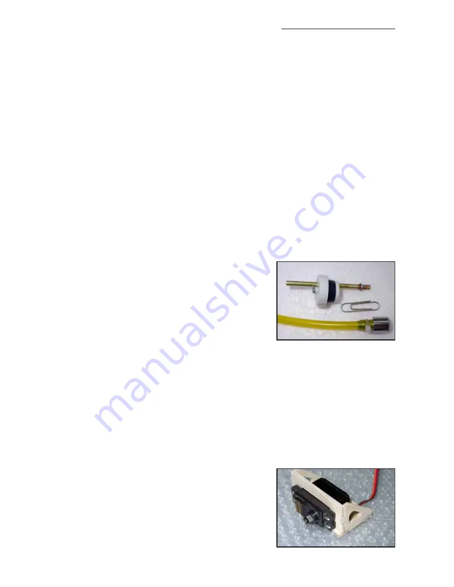
Fit the correct stopper to the fuel tank for the fuel type used. (If using Dubro tank the gasoline
stopper has a small ‘O’ moulded in the top of it). We use the excellent ‘Tygon’ brand of fuel tub-
ing for all our models. It is totally gasoline and kerosene-proof, and does not go hard and crack
with age. Secure the feed tube inside the tank to the clunk with a small cable tie. If the tube is
even a little loose on the brass tubes though the stopper it will come off at just the wrong moment
and your engine will quit. So solder some small rings onto both ends of the brass tubing (easily
made from the soft wire of a paperclip wrapped around a small screwdriver) and secure with a
fuel-line clamp or cable-tie. Don’t miss this small detail - it could cost you your plane !
We use the normal 3-tube plumbing system, one from the clunk to feed the motor, one out of the
bottom of the plane (vent/overflow - leave open) and one at the top for filling (close for flight).
Throttle servo
Included in the kit is a CNC milled plywood throttle servo
mount, and you can fit this in any suitable position for your
motor set-up. On the prototypes we fixed this inside the
motor dome above the headers (see photo) which gives a
nice short throttle linkage. However, we advise you
not
to
mount it directly on the back of the firewall as engine vibra-
13
Throttle servo mount