P M 13 7 9
6
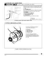
Obtain gas cylinder and chain to running gear, wall, or other
stationary support so cylinder can not fall and break off valve.
1.- CAP.
2.- CYLINDER VALVE.
Remove cap, stand to side of valve, and open valve slightly.
Gas flow blows dust and dirt from valve. Close valve.
3.- CYLINDER.
4.- REGULATOR /FLOWMETER.
5.- GAS HOSE CONNECTION.
6.- FLOW ADJUST.
Typical flow rate is 20 cfh ( Cubic Feet per Hour).
FIGURE 3-6 SHIELDED GAS CONNECTIONS.
1
2
3
6
5
4
3-6 SHIELDED GAS CONNECTIONS.
WARNING
SEE SAFETY SIGNAL AT THE BEGINING THIS M ANUAL
28.5, 15.8mm (1-1/8",5/8")
Tools Needed
3-7 SPOOL WIRE INSTALLATION.
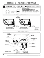
For 8" and 12" (standard) wire spools
turn unit off and disconnect it.
1.- Hub spool.
2.- Pin of Hub spool.
3.- Wire spool / Reel.
4.- Hud spool cap.
Turn the hub spool cap clockwise
and remove it. Install the wire spool, be
sure the hub spool´s pin enters one of the
holes of the wire spool. Reinstall the hub
spool cap.
1
2
3
4
FIGURE 3-7 SPOOL WIRE INSTALLATION.

