background image

Removal and Replacement Procedures  

2-25

CD-ROM Drive

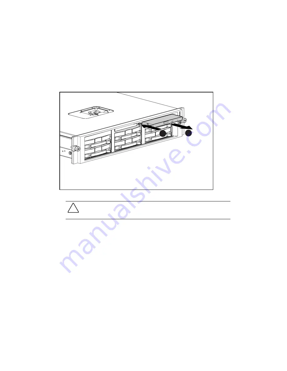
To eject the CD-ROM drive:


1.


Power down the server. See the “Powering Down the Server” section in this chapter.


2.


Push the ejection button 

.


3.


Pull the CD-ROM drive out the CD MultiBay 

.

2

1

Figure 2-24.  Ejecting the CD-ROM drive

CAUTION:

  Always populate the CD MultiBay with either a CD-ROM drive or a CD blank.

Operating the server without installing a CD-ROM drive or CD blank results in improper airflow
and improper cooling that can lead to thermal damage.

To replace the CD-ROM drive, slide the CD-ROM drive into the CD MultiBay until it is fully
seated.

Содержание ProLiant DL380 Generation 2

Страница 1: ...ProLiant DL380 Generation 2 Server Maintenance and Service Guide Second Edition June 2001 Part Number 203840 002 Spare Part Number 228520 001 Compaq Computer Corporation...

Страница 2: ...and other countries All other product names mentioned herein may be trademarks of their respective companies Compaq shall not be liable for technical or editorial errors or omissions contained herein...

Страница 3: ...2 Server Warnings and Cautions 2 3 Preparation Procedures 2 3 Extending the Server from the Rack 2 4 Powering Down the Server 2 5 Removing the Server from the Rack 2 6 Hot Plug Procedures 2 6 Hot Plu...

Страница 4: ...ontroller 2 50 Battery 2 51 System Board 2 53 Rear Fan Bracket 2 56 SCSI Cable Short 2 57 CD MultiBay Cable 2 58 Power Button LED Cable 2 59 System Cables 2 60 PCI Hot Plug Backplane Cable 2 61 Option...

Страница 5: ...4 18 SCSI Interlock Disable Switch 4 19 NMI Switch 4 19 System Maintenance Switch 4 20 Chassis ID Switch 4 20 Jumpers 4 21 Chapter 5 Specifications System Unit 5 2 Hot Plug Power Supply 5 3 Memory 5 3...

Страница 6: ...at failure to follow directions in the warning could result in bodily harm or loss of life CAUTION Text set off in this manner indicates that failure to follow directions could result in damage to equ...

Страница 7: ...plug is an important safety feature Plug the power cord into a grounded earthed electrical outlet that is easily accessible at all times CAUTION The computer is designed to be electrically grounded To...

Страница 8: ...strated Parts Catalog This chapter provides the illustrated parts breakdown and spare parts list for the Compaq ProLiant DL380 Generation 2 server See Table 1 1 and Table 1 2 for the names of referenc...

Страница 9: ...ts Table 1 1 Mechanical Components Spare Parts List Item Description Part Number Spare Part Number 1 Access panel top cover 218377 001 228523 001 2 Front bezel 218381 001 228512 001 3 Tape drive blank...

Страница 10: ...art Number Spare Part Number System Components 7 Hot plug fan 60 mm 218382 001 228513 001 8 Front fan bracket 6 bay 218383 001 228514 001 9 Rear fan bracket 2 bay 218667 001 228493 001 10 Hot plug pow...

Страница 11: ...d 010963 001 228503 001 Mass Storage Devices 22 Diskette drive slimline 1 44 MB 235168 001 228507 001 23 CD ROM drive IDE 24X 222837 001 228508 001 Cables 24 SCSI cable kit 228517 001 SCSI cable short...

Страница 12: ...03 30 CD ejector assembly 233905 001 237158 001 31 PCI expansion board ejector divider 218976 001 228515 001 32 Battery 3 3 V lithium 334149 001 179322 001 33 Country kit 195313 001 228526 001 34 Retu...

Страница 13: ...sensitive devices or microcircuitry Proper packaging and grounding techniques are necessary to prevent damage To prevent electrostatic damage observe the following precautions Transport products in s...

Страница 14: ...elephone or telecommunications connectors into this receptacle CLASS 1 LASER PRODUCT This label or equivalent is located on the surface of your CD ROM drive This label indicates that the product is cl...

Страница 15: ...e server from power fluctuations and temporary interruptions with a regulating uninterruptible power supply UPS This device protects the hardware from damage caused by power surges and voltage spikes...

Страница 16: ...il release latches engage Figure 2 1 Extending the server from the rack WARNING To reduce the risk of personal injury be careful when pressing the server rail release latches and sliding the component...

Страница 17: ...tely disconnect power from the system CAUTION Electrostatic discharge can damage electronic components Be sure you are properly grounded before beginning any installation procedure For more informatio...

Страница 18: ...e Server section in this chapter 2 Loosen the front panel thumbscrews that secure the server faceplate to the front of the rack 3 Remove the server from the rack Refer to the setup and installation gu...

Страница 19: ...ot Plug SCSI Hard Drive Replacement Guidelines from the Compaq Servers Troubleshooting Guide To remove a hot plug SCSI hard drive 1 Press the release button to unlock the lever on the hard drive 2 Pul...

Страница 20: ...rive bay 2 1 Figure 2 5 Removing a hard drive blank CAUTION Always populate hard drive bays with either a hard drive or hard drive blank Operating the server without installing a hard drive or hard dr...

Страница 21: ...2 Figure 2 6 Removing the CD blank CAUTION Always populate the CD MultiBay with either a CD ROM drive or CD blank Operating the server without installing a CD ROM drive or CD blank results in improper...

Страница 22: ...ape drive out of the bay 1 2 Figure 2 7 Removing a universal hot plug tape drive CAUTION Always populate the tape drive bay with either a tape drive or hard drive blank and tape drive blank Operating...

Страница 23: ...nstalled in the bay see the Hard Drive Blank section in this chapter 2 Squeeze the middle of the tape drive blank 3 Pull to remove the blank 2 1 Figure 2 8 Removing the tape drive blank CAUTION Always...

Страница 24: ...hot plug power supplies are installed you can replace the failed power supply without powering down the server Proceed with step 3 3 Press the locking latch 4 Pull the power supply out of the bay 1 2...

Страница 25: ...the bay 1 2 Figure 2 10 Removing the power supply blank CAUTION Always populate power supply bays with either a power supply or blank Operating the server without installing a power supply or blank r...

Страница 26: ...out the access panel results in improper airflow and improper cooling that can lead to thermal damage To remove the access panel 1 Extend or remove the server from the rack See the Preparation Procedu...

Страница 27: ...ement Procedures 2 15 4 Slide the access panel toward the rear of the unit about 1 25 cm 0 5 inch and lift to remove the panel Figure 2 12 Removing the access panel Reverse steps 1 through 4 to replac...

Страница 28: ...G If the fan zone is not fully populated you must power down the server See the Powering Down the Server section in this chapter G If the fan zone is fully populated you can replace the failed fan wit...

Страница 29: ...nel See the Access Panel section in this chapter 3 Lift the air baffle Figure 2 14 Removing the air baffle CAUTION Always install the air baffle after completing hardware installation or maintenance p...

Страница 30: ...edures section in this chapter 2 Remove the access panel See the Access Panel section in this chapter 3 Open the PCI riser cage door 4 Lift and remove the PCI shipping bracket 2 1 Figure 2 15 Removing...

Страница 31: ...the rack See the Preparation Procedures section in this chapter 2 Remove the access panel See the Access Panel section in this chapter 3 Open the PCI riser cage door Figure 2 16 Opening the PCI riser...

Страница 32: ...an expansion board from slots 2 and 3 1 Extend or remove the server from the rack See the Preparation Procedures section in this chapter 2 Remove the access panel See the Access Panel section in this...

Страница 33: ...he PCI slot release lever to unlock it 8 Open the PCI slot release lever 9 Remove the expansion board from the slot G If the expansion board is installed in slot 2 grasp the PCI expansion board ejecto...

Страница 34: ...flow and cooling that can lead to thermal damage Reverse steps 1 through 9 to replace the expansion board Expansion Slot Cover Slots 2 and 3 To remove an expansion slot cover from slots 2 and 3 1 Exte...

Страница 35: ...r out of the slot 2 1 3 Figure 2 22 Removing the expansion slot cover from slot 3 CAUTION Always install either an expansion board or an expansion slot cover Operating the server without an expansion...

Страница 36: ...rver from the rack See the Preparation Procedures section in this chapter 3 Remove the access panel See the Access Panel section in this chapter 4 Remove any hot plug SCSI hard drives if installed See...

Страница 37: ...D ROM drive out the CD MultiBay 2 1 Figure 2 24 Ejecting the CD ROM drive CAUTION Always populate the CD MultiBay with either a CD ROM drive or a CD blank Operating the server without installing a CD...

Страница 38: ...the server from the rack See the Preparation Procedures section in this chapter 3 Remove the access panel See the Access Panel section in this chapter 4 Disconnect the diskette interface cable from th...

Страница 39: ...ss Panel section in this chapter 4 Remove the CD ROM drive or CD blank G If a CD ROM drive is installed in the bay see the CD ROM Drive section in this chapter G If a CD blank is installed in the bay...

Страница 40: ...ess Panel section in this chapter 4 Remove the CD ROM drive or CD blank G If a CD ROM drive is installed in the bay see the CD ROM Drive section in this chapter G If a CD blank is installed in the bay...

Страница 41: ...driver to remove the ejector assembly screw 10 Press and hold the ejection button 11 Slide the ejector assembly toward the rear of the chassis and lift 1 2 Figure 2 28 Removing the CD ejector assembly...

Страница 42: ...chapter 3 Remove the access panel See the Access Panel section in this chapter 4 Remove all the hot plug fans in the bracket See the Hot Plug Fan section in this chapter 5 Press inward on the release...

Страница 43: ...ves See the Hot Plug SCSI Hard Drive section in this chapter 5 Remove the tape drive if installed See the Universal Hot Plug Tape Drive section in this chapter 6 Remove all hot plug fans from the fron...

Страница 44: ...stem components To remove the PCI riser cage 1 Power down the server See the Powering Down the Server section in this chapter 2 Disconnect any external cables connected to expansion boards 3 Extend or...

Страница 45: ...Removal and Replacement Procedures 2 33 8 Lift the PCI riser cage Figure 2 32 Removing the PCI riser cage Reverse steps 1 through 7 to replace the PCI riser cage...

Страница 46: ...the PCI Riser Cage section in this chapter 5 Disconnect any cables connecting the expansion board to the PCI riser cage 6 Remove the PCI shipping bracket if installed See the PCI Shipping Bracket sect...

Страница 47: ...ccess Panel section in this chapter 4 Remove the PCI riser cage See the PCI Riser Cage section in this chapter 5 Remove the expansion slot thumbscrew 6 Remove the expansion slot cover from slot 1 1 2...

Страница 48: ...e the Access Panel section in this chapter 4 Remove the PCI riser cage See the PCI Riser Cage section in this chapter 5 Remove the three Torx T 15 screws that secure the expansion board ejector divide...

Страница 49: ...Access Panel section in this chapter 4 Remove the expansion board or slot cover from the slot G If an expansion board is installed in the slot see the Expansion Board Slots 2 and 3 section in this cha...

Страница 50: ...Service Guide 8 From the rear of the PCI riser cage press the slot release lever to unseat it 9 Rotate the slot release lever out of the chassis 1 2 Figure 2 37 Removing the PCI slot release lever Re...

Страница 51: ...remove the server from the rack See the Preparation Procedures section in this chapter 3 Remove the access panel See the Access Panel section in this chapter 4 Press down on the locking tab that secur...

Страница 52: ...nt DL380 Generation 2 Server Maintenance and Service Guide 7 Slide the lightpipe out of the chassis Figure 2 39 Sliding the lightpipe out of the chassis Reverse steps 1 through 7 to replace the PCI li...

Страница 53: ...is chapter 4 Remove all hot plug fans in the front fan bracket See the Hot Plug Fan section in this chapter 5 Remove the front fan bracket See the Front Fan Bracket section in this chapter 6 Remove al...

Страница 54: ...e thumbscrew that secures the power converter module to the chassis 9 Slide and lift the power converter module off the chassis 1 2 Figure 2 41 Removing the power converter module from the chassis cab...

Страница 55: ...r from the rack See the Preparation Procedures section in this chapter 3 Remove the access panel See the Access Panel section in this chapter 4 Disconnect the power button LED cable from the power but...

Страница 56: ...o DIMMs installed in DIMM slots 1A and 4A 4 Open the DIMM slot latches 5 Remove the DIMM from the slot 2 1 1 Figure 2 43 Removing a DIMM CAUTION To ensure proper configuration of DIMMs refer to Chapte...

Страница 57: ...n this chapter 3 Remove the access panel See the Access Panel section in this chapter 4 Remove the air baffle See the Air Baffle section in this chapter 5 Open the locking lever on the heatsink retain...

Страница 58: ...or 1 2 3 Figure 2 45 Removing the heatsink and processor from the system board To replace a processor CAUTION Processor socket 1 must be populated with a processor at all times The system fails to boo...

Страница 59: ...stalling the processor CAUTION Always use a new heatsink with thermal interface material when replacing processors Failure to use new components may result in damage to the processor 4 Remove the plas...

Страница 60: ...p 1 2 3 Figure 2 48 Installing the heatsink and heatsink retaining clip CAUTION PPM slots must be populated when processors are installed If PPM slots are not populated the system does not boot 8 Inst...

Страница 61: ...ion in this chapter 3 Remove the access panel See the Access Panel section in this chapter 4 Open the latches on the sides of the PPM slots 5 Lift the PPM out of the slot 1 2 1 Figure 2 49 Removing a...

Страница 62: ...this chapter 5 Turn each of the four anchor pins one quarter turn counterclockwise 6 Lift the controller off the system board 2 1 Figure 2 50 Removing the Smart Array 5i Controller IMPORTANT In the d...

Страница 63: ...r Replace only with the spare designated for this product CAUTION Removing the lithium battery causes the system to lose the BIOS settings Reconfigure the BIOS settings when you replace the battery CA...

Страница 64: ...Server Maintenance and Service Guide 5 Remove the battery Figure 2 51 Removing the battery Reverse steps 1 through 5 to replace the battery After replacing the battery you must use the ROM Based Setup...

Страница 65: ...lug Fan section in this chapter 7 Remove the front fan bracket See the Front Fan Bracket section in this chapter 8 Remove any SDRAM DIMMs See the DIMMs section in this chapter 9 Remove the processors...

Страница 66: ...Service Guide 14 Loosen the system board thumbscrew Figure 2 52 Loosening the system board thumbscrew 15 Identify the alignment keys and keyhole locations through on the system board 4 1 2 3 6 7 5 Fi...

Страница 67: ...atsink with thermal interface material when replacing processors on the new system board Failure to use new components may result in damage to the processor For more information see the Processors sec...

Страница 68: ...ove all hot plug fans See the Hot Plug Fan section in this chapter 7 Remove the front fan bracket See the Front Fan Bracket section in this chapter 8 Remove the system board See the System Board secti...

Страница 69: ...e server from the rack See the Preparation Procedures section in this chapter 3 Remove the access panel See the Access Panel section in this chapter 4 Disconnect the SCSI cable from the SCSI backplane...

Страница 70: ...r 2 Extend or remove the server from the rack See the Preparation Procedures section in this chapter 3 Remove the access panel See the Access Panel section in this chapter 4 Disconnect the CD MultiBay...

Страница 71: ...he server from the rack See the Preparation Procedures section in this chapter 3 Remove the access panel See the Access Panel section in this chapter 4 Disconnect the power button LED cable from the S...

Страница 72: ...ocedures section in this chapter 3 Remove the access panel See the Access Panel section in this chapter 4 Remove the fans from the front fan bracket See the Hot Plug Fan section in this chapter 5 Remo...

Страница 73: ...hapter 3 Remove the access panel See the Access Panel section in this chapter 4 Remove the PCI riser cage See the PCI Riser Cage section in this chapter 5 Disconnect the PCI Hot Plug backplane cable f...

Страница 74: ...ser cage See the PCI Riser Cage section in this chapter 5 Disconnect the Remote Insight Lights Out Edition interface cable from the PCI riser board 6 Disconnect the Remote Insight Lights Out Edition i...

Страница 75: ...ove the server from the rack See the Preparation Procedures section in this chapter 3 Remove the access panel See the Access Panel section in this chapter 4 Disconnect the SCSI cable from the SCSI bac...

Страница 76: ...Chapter 3 Diagnostic Tools This chapter is an overview of software and firmware diagnostic tools that are available for configuring monitoring and managing ProLiant DL380 Generation 2 servers...

Страница 77: ...s the error information to the IML resets the server and tries to restart the operating system Run RBSU and set ASR 2 to enable this tool Compaq Diagnostics Compaq Diagnostics tests and verifies opera...

Страница 78: ...er or SCO Unixware operating systems If a significant change occurs between data gathering intervals the survey utility marks the previous information and overwrites the survey text files to reflect t...

Страница 79: ...talling an operating system Configure ports and IRQs if required Run RBSU by pressing the F9 key during POST ROMPaq Utility The ROMPaq Utility checks the system and provides a choice of available ROM...

Страница 80: ...Chapter 4 Connectors LED Indicators Switches and Jumpers This chapter explains the location and function of system connectors internal and external LEDs system board switches and jumpers...

Страница 81: ...rs Figure 4 1 and Table 4 1 show the connectors on the rear panel of a ProLiant DL380 Generation 2 server 1 3 5 8 10 9 7 4 2 6 3 2 Figure 4 1 Rear panel connectors Table 4 1 Rear Panel Connectors Item...

Страница 82: ...d Connectors Item Description Item Description PPM slot 2 Diskette drive system connector PPM slot 1 Battery PCI riser cage connector Fan 6 connector Smart Array 5i Controller System power connector S...

Страница 83: ...tains several sets of LEDs that indicate the status and settings of hardware components This section explains the following types of LEDs Front panel Hot plug SCSI hard drive PCI riser cage PCI Hot Pl...

Страница 84: ...th Red System critical Amber System degraded Green Normal External health power supply Red Critical power supply failure Amber Power redundancy failure Green Normal NIC 1 link activity NIC 2 link acti...

Страница 85: ...icators may vary depending on the status of other drives in the array Use Figure 4 4 and Table 4 4 to analyze the status of each hot plug SCSI hard drive WARNING To avoid personal injury read the Hot...

Страница 86: ...re alert is received see the following section for details and the drive is attached to an array controller The drive is not configured as part of an array Or If this drive is part of an array then a...

Страница 87: ...3 are operating at 66 or 33 MHz The AC power connected LED indicates when the AC power is connected to the server Use Figure 4 5 and Table 4 5 to identify the PCI riser cage LEDs 1 2 Figure 4 5 PCI ri...

Страница 88: ...o identify the LEDs 3 2 1 2 3 4 Figure 4 6 PCI Hot Plug button LEDs Table 4 6 PCI Hot Plug LEDs Item LED Description Status Slot 3 power green On Power is applied to the slot Flashing Power is cycling...

Страница 89: ...ar panel has two LEDs Use Figure 4 7 and Table 4 7 to identify the location and status of the LEDs 3 2 1 2 Figure 4 7 RJ 45 network connector LEDs Table 4 7 RJ 45 Network Connector LEDs Item LED Descr...

Страница 90: ...tch The rear unit identification LED switch offers a visual reference for service personnel Figure 4 8 Figure 4 8 Rear unit identification LED switch The rear unit identification LED switch indicates...

Страница 91: ...ated adjacent to the AC inlet Figure 4 9 Figure 4 9 Hot plug power supply LED When the power supply LED is off the following conditions may exist The AC power is unavailable The power supply has faile...

Страница 92: ...ot Plug Fan LED Each of the hot plug fans contains a dual color LED Figure 4 10 Figure 4 10 Hot plug fan LED The hot plug fan LED indicates the following conditions Green The fan is operating normally...

Страница 93: ...11 Power converter module LED The power converter module LED indicates the following conditions Amber The power converter module has failed Off The power converter module is functioning System Board L...

Страница 94: ...Amber PPM failed Off Normal Overtemperature Amber Temperature has exceeded OS cautionary level or critical hardware level Off Temperature is OK PPM 1 failure Amber PPM failed Off Normal Riser SCSI in...

Страница 95: ...ystem LED and Color Internal Health LED Color Status Red Processor in socket X has failed Processor X has failed over to offline spare Processor X is not installed in the socket Processor X is unsuppo...

Страница 96: ...memory exists in another bank DIMM failure all slots in all banks Amber Red No valid or usable memory is installed in the system Overtemperature Amber Red System has reached the operating system caut...

Страница 97: ...ings or perform advanced diagnostic procedures The following sections explain the functions of each switch Figure 4 13 and Table 4 10 identify switch locations on the system board 2 1 3 4 Figure 4 13...

Страница 98: ...rray 5i Controller On Interlock failure applies only to the PCI riser 2 Reserved NMI Switch Crash dump analysis is an essential part of eliminating reliability problems such as hangs or crashes in ope...

Страница 99: ...On System configuration is locked and cannot be modified 3 Rack mount indicator Off System is in a tower configuration On System is in a rack mounted configuration 4 Enable diskette boot Off RBSU cont...

Страница 100: ...ntains one two pin bootblock flash jumper It enables the user to configure the system board for a bootblock flash of the system ROM Figure 4 14 Figure 4 14 Bootblock flash jumper To perform a bootbloc...

Страница 101: ...pter provides operating and performance specifications for ProLiant DL380 Generation 2 server components and hardware including System unit Hot plug power supply Memory 1 44 MB diskette drive CD ROM d...

Страница 102: ...to 240 VAC Rated input frequency 50 Hz to 60 Hz Rated input current 6 A 110 V 3 A 220 V Rated input power 600 W Power supply output Rated steady state power 400 W Maximum peak power 400 W Temperature...

Страница 103: ...110 V to 3 A 220 V Output Power Steady state power 400 W Maximum peak power 400 W Dielectric voltage withstand Input to output 2 000 VAC minute Input to ground 2 000 VAC minute Memory Table 5 3 SDRAM...

Страница 104: ...On Read write capacity per diskette High density 1 44 MB Low density 720 KB Drives supported 1 Drive height One third height Drive rotation 300 rpm Transfer rate High 500 Kb s Low 250 Kb s Bytes sect...

Страница 105: ...mm 0 50 in Depth 123 08 mm 5 20 in Width 132 08 mm 5 20 in Weight 0 34 kg 0 75 lb Data transfer rate Sustained 150 KB s sustained 1X 1500 4800 KB s 10X to 32X Burst 4 0 MB s Access times typical Full...

Страница 106: ...1 0 in One third 1 0 in Size 3 5 in 3 5 in 3 5 in 3 5 in Interface Wide Ultra3 Wide Ultra3 Wide Ultra3 Wide Ultra3 Transfer rate 160 MB sec 160 MB sec 160 MB sec 160 MB sec Rotational speed 10 000 RP...

Страница 107: ...4 Array Diagnostics Utility ADU access 3 2 description 3 2 Automatic Server Recovery 2 ASR 2 access 3 2 description 3 2 B backplanes PCI Hot Plug 2 61 SCSI See SCSI backplane baffle air airflow 2 17 i...

Страница 108: ...See Remote Insight Lights Out Edition interface cable SCSI backplane 2 31 2 41 SCSI power See SCSI power cable SCSI long See SCSI cable long SCSI short See SCSI cable short system power See system po...

Страница 109: ...4 2 power supply signal 2 41 RJ 45 4 2 SCSI power 2 41 serial 4 2 Smart Array 5i Controller 4 3 system power 2 41 4 3 USB 4 2 VHDCI SCSI 4 2 video 4 2 country kit part number 1 5 spare part number 1 5...

Страница 110: ...See universal hot plug tape drive E ejecting CD blank 2 9 CD ROM drive 2 25 ejection button 2 9 2 25 2 29 ejector assembly CD installing 2 29 part number 1 5 removing 2 28 replacing 2 29 spare part n...

Страница 111: ...oving 2 7 replacing 2 7 SCSI IDs 2 7 specifications 5 6 hardware kit contents 1 5 spare part number 1 5 health LEDs external 4 5 internal 4 5 heatsink retaining clips installing 2 48 removing 2 45 rep...

Страница 112: ...lug 2 16 front bezel 2 24 front fan bracket 2 30 hard drive blank 2 8 hard drives 2 7 heatsink retaining clips 2 48 heatsinks 2 48 hot plug fans 2 16 hot plug power supplies 2 12 LED CD ROM drive syst...

Страница 113: ...6 external health 4 5 fans hot plug 4 13 fault status 4 6 front unit identification LED switch 2 5 4 5 health external 4 5 health internal 4 5 hot plug fans 4 13 hot plug power supplies 4 12 hot plug...

Страница 114: ...ystem cable 1 4 maintenance and service guide 1 5 PCI expansion board ejector divider 1 5 PCI Hot Plug backplane cable 1 4 PCI lightpipe 1 5 PCI lightpipe cover 1 5 PCI riser cage 1 3 PCI riser cage d...

Страница 115: ...PCI Hot Plug LEDs slot 2 fault 4 9 slot 2 power 4 9 slot 3 fault 4 9 slot 3 power 4 9 PCI lightpipe See also PCI Hot Plug LEDs installing 2 40 part number 1 5 removing 2 39 replacing 2 40 PCI lightpi...

Страница 116: ...g 2 12 replacing 2 12 spare part number 1 3 specifications 5 3 power supply blank installing 2 13 part number 1 2 removing 2 13 replacing 2 13 spare part number 1 2 power supply signal cable disconnec...

Страница 117: ...2 7 hard drive blank 2 8 heatsink retaining clips 2 45 heatsinks 2 46 hot plug fans 2 16 hot plug power supplies 2 12 LED CD ROM drive system cable 2 60 memory 2 44 PCI expansion board ejector divider...

Страница 118: ...2 11 universal hot plug tape drive 2 10 requirements drivers internal health LED 4 16 PCI Hot Plug 2 7 hot plug procedures 2 6 input See input requirements local occupational and health safety 2 2 ret...

Страница 119: ...8 Smart Array 5i Controller connector 4 3 installing 2 50 part number 1 4 removing 2 50 replacing 2 50 spare part number 1 4 SmartStart Diskette Builder utility access 3 4 description 3 4 SmartStart f...

Страница 120: ...skette drive system cable installing 2 60 LED CD ROM drive See LED CD ROM drive system cable removing 2 60 replacing 2 60 system components 1 3 system maintenance switch default settings 4 20 defined...

Страница 121: ...2 6 4 11 universal hot plug tape drive installing 2 10 populating bays 2 10 2 11 removing 2 10 replacing 2 10 USB connectors 4 2 utilities Compaq Diagnostics 3 2 Compaq Insight Manager XE 3 2 Compaq...

Отзывы: