d
.
Switch cover (see
Switch cover on page 69
)
e
.
Display assembly (see
Display assembly on page 71
)
f
.
Top cover (see
Top cover on page 80
)
g
.
Wireless switch board (see
Wireless switch board on page 85
)
h
.
Audio board (see
Audio board on page 88
)
i
.
Bluetooth module (see
Bluetooth module on page 89
)
j
.
USB board (see
USB board on page 90
)
k
.
System board (see
System board on page 95
)
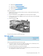
Remove the ExpressCard assembly:
1
.
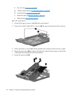
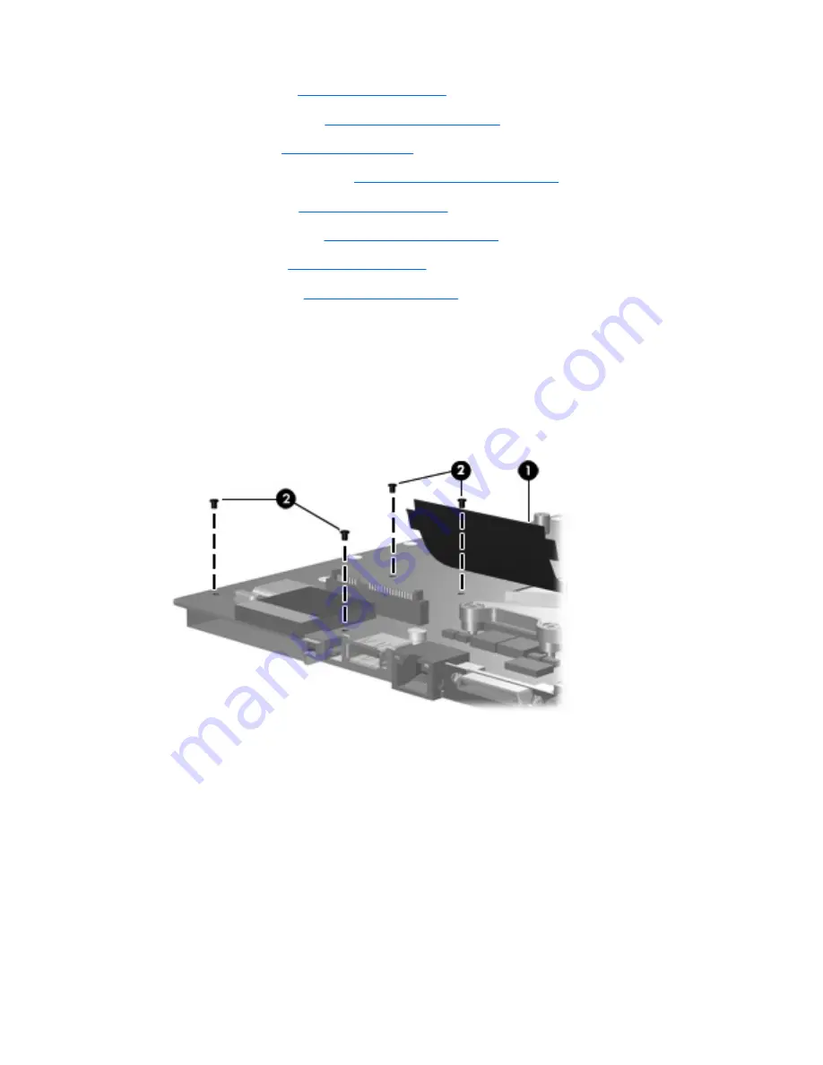
Turn the system board upside down, with the RJ-45 connector toward you.
2
.
Lift the insulation material
(1)
from the system board to expose the ExpressCard assembly rear
screws.
3
.
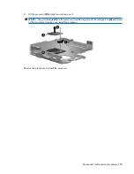
Remove the four Phillips PM2.0×4.0 screws
(2)
that secure the ExpressCard assembly to the system
board.
4
.
Turn the system board right-side up, with the RJ-45 connector toward you.
98 Chapter
4
Removal and replacement procedures


