6
.
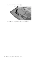
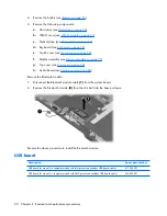
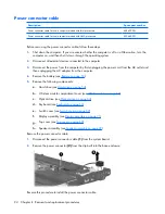
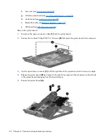
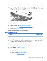
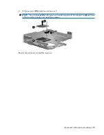
If it is necessary to replace the modem module cable, remove the RJ-11 connector
(1)
from the clip
built into the base enclosure.
7
.
Remove the modem module cable
(2)
from the routing channel built into the base enclosure. The
modem module cable is included in the Cable Kit, spare part number 430474-001, and is available
separately using spare part number 455847-001.
When replacing the system board, be sure that the following components are removed from the defective
system board and installed on the replacement system board:
●
ExpressCard assembly (see
ExpressCard assembly on page 97
)
●
Fan/heat sink assembly (see
Fan/heat sink assembly on page 100
)
●
Processor (see
Processor on page 103
)
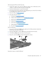
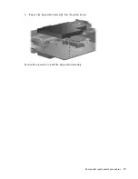
Reverse the preceding procedure to install the system board.
ExpressCard assembly
Description
Spare part number
ExpressCard assembly
417112-001
Before removing the ExpressCard assembly, follow these steps:
1
.
Shut down the computer. If you are unsure whether the computer is off or in Hibernation, turn the
computer on, and then shut it down through the operating system.
2
.
Disconnect all external devices connected to the computer.
3
.
Disconnect the power from the computer by first unplugging the power cord from the AC outlet and
then unplugging the AC adapter from the computer.
4
.
Remove the battery (see
Battery on page 53
).
5
.
Remove the following components:
a
.
Hard drive (see
Hard drive on page 54
)
b
.
Optical drive (see
Optical drive on page 64
)
c
.
Keyboard (see
Keyboard on page 66
)
Component replacement procedures 97


