


6–8
Maintenance and Service Guide
Specifications
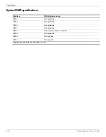
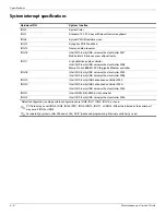
System interrupt specifications
Hardware IRQ
System function
IRQ0
System timer
IRQ1
Standard 101-/102-key or Microsoft natural keyboard
IRQ8
System CMOS/real-time clock
IRQ12
Synaptics PS/2 TouchPad
IRQ13
Numeric data processor
IRQ16
Intel ICH9 family USB universal host controller 2937
Mobile Intel 4 Series express chipset family
IRQ17
High definition audio controller
Intel ICH9 family USB universal host controller 2938
Marvell Yukon 88E8072 PCIE-gigabit Ethernet controller
IRQ18
Intel ICH9 family USB universal host controller 2939
Intel ICH9 family USB universal host controller 2936
IRQ19
Intel ICH9 family USB2 enhanced controller 293C
IRQ20
Intel ICH9 family USB2 enhanced controller 293A
Intel ICH9 family USB universal host controller 2934
IRQ21
Intel ICH9M-E/M SATA AHCI controller
IRQ22
Intel ICH9 family USB universal host controller 2935
*Default configuration; audio possible configurations are IRQ5, IRQ7, IRQ9, IRQ10, or none.
✎
PC Cards may assert IRQ3, IRQ4, IRQ5, IRQ7, IRQ9, IRQ10, IRQ11, or IRQ15. Either the infrared or the serial port
may assert IRQ3 or IRQ4.
✎
For operating systems after Windows 2000, APIC (Advanced programming interrupt controller) is used.
Содержание Presario CQ35
Страница 2: ......
Страница 8: ...vii Maintenance and Service Guide ...
Страница 24: ...3 2 Maintenance and Service Guide Illustrated parts catalog Computer major components ...
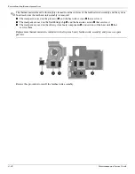
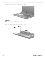
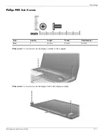
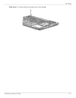
Страница 113: ...Screw listing Maintenance and Service Guide 7 13 Where used 2 screws that secure the system board to the computer ...


