Compaq Evo w4000 CMT Скачать руководство пользователя страница 58

Hardware Reference Guide

D–3

Security Lock Provisions

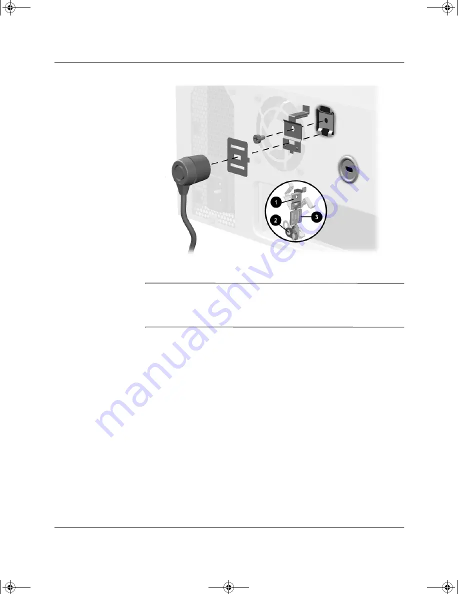
Installing a Cable Lock with a Compaq Type 2 Bracket (may vary 
by model)

Å

WARNING: 

To avoid injury, use care in handling the separated pieces of 

the security bracket; metal edges may be sharp. Be sure to install the 
bracket so that sharp edges do not extend from the edges of the 
computer chassis.

244947-002.book  Page 3  Thursday, November 15, 2001  10:05 AM

Содержание Evo w4000 CMT

Страница 1: ...vo Workstation W4000 Convertible Minitower Models Document Part Number 244947 002 January 2002 This book provides basic information for upgrading this series of computers 244947 002 book Page i Thursd...

Страница 2: ...out warranty of any kind and is subject to change without notice The warranties for Compaq products are set forth in the express limited warranty statements accompanying such products Nothing herein s...

Страница 3: ...Minitower to a Desktop Configuration 1 7 Changing from a Desktop to a Minitower Configuration 1 10 2 Hardware Upgrades Installation Sequence 2 1 Smart Cover Lock 2 2 Using the Smart Cover FailSafe Ke...

Страница 4: ...the Cable Select Feature with Ultra ATA Devices B 1 Guidelines for Installing Ultra ATA Devices B 2 SCSI Devices B 3 Guidelines for Using SCSI Devices B 3 Guidelines for Installing Optional SCSI Devi...

Страница 5: ...ts F Routine Computer Care and Shipping Preparation Routine Computer Care F 1 CD ROM Drive Precautions F 2 Operation F 2 Cleaning F 2 Safety F 2 Shipping Preparation F 3 Index 244947 002 book Page v T...

Страница 6: ...ay vary depending on your model For a complete listing of the hardware and software installed on your computer run Compaq Diagnostics for Windows or the INSPECT utility available on some models Instru...

Страница 7: ...Diskette Drive Activity Light 6 Diskette Eject Button 2 Dual State Power Button 7 Hard Drive Activity Light 3 Power On Light 8 Headphone Connector 4 CD ROM Eject Button 9 USB Connector 5 CD ROM Drive...

Страница 8: ...tor 8 Monitor Connector 3 Keyboard Connector 9 Headphone Line out Connector 4 Universal Serial Bus USB Connector Line in Audio Connector 5 Serial Connector COM1 q Microphone Connector 6 Ethernet RJ 45...

Страница 9: ...other keys to perform other functions See following section 3 Alt Key Used in combination with another key its effect depends on the application software you are using 4 Application Key Used like the...

Страница 10: ...wn Ctrl and Alt while pressing Delete allows you to restart your computer 7 Num Lock light Indicates whether the Num Lock feature is on or off 8 Caps Lock light Indicates whether the Caps Lock feature...

Страница 11: ...er to the Readme admin txt file Easy Access Paper Icon Insert The paper icon insert functions as a visual aid in identifying the programmed destination of each Easy Access Button Whenever you reprogra...

Страница 12: ...a Desktop Configuration 1 Shut down the operating system properly then turn off the computer and any external devices Disconnect the power cord from the power outlet and disconnect any external devic...

Страница 13: ...k pull the drives out of the drive bay 7 Before you install each drive into the chassis turn it so that it is perpendicular to the internal 3 5 inch drive The bottom of the drive should be parallel to...

Страница 14: ...ecure it CAUTION The use of unnecessary force may result in damage to the drives 9 Reconnect all power and data cables to the drives in the 5 25 inch drive bays 10 Remove the subpanel as described in...

Страница 15: ...anging from a Minitower to a Desktop Configuration 12 Replace the subpanel front bezel and the computer access panel 13 Reconnect the external equipment Changing from a Desktop to a Minitower Configur...

Страница 16: ...e 5 25 inch drive bays 5 To release the drives from the 5 25 inch drive bay press the short yellow drivelock 1 as shown Activating the Drivelock Shown from the Rear of the Chassis 6 While pressing the...

Страница 17: ...in the bay nearest the internal 3 5 inch drives in the minitower configuration for proper clearance within the chassis Installing a Drive in the Minitower Configuration 8 Gently slide the drive into t...

Страница 18: ...ng the subpanel away at an angle could damage the pins that align it within the front bezel 11 Remove the chrome logo plate from the subpanel and reposition it rotate it 180 with the logo plate in the...

Страница 19: ...k and or hot surfaces be sure to disconnect the power cord from the wall outlet and allow the internal system components to cool before touching WARNING To reduce the risk of electrical shock fire or...

Страница 20: ...onal feature included on select models only The Smart Cover Lock is a software controllable cover lock controlled by the setup password This lock prevents unauthorized access to the internal component...

Страница 21: ...ll the appropriate number listed in the warranty To open the access panel 1 Turn off the computer and any external devices 2 Disconnect the power cord from the power outlet and disconnect any external...

Страница 22: ...r and any external devices 3 Disconnect the power cord from the power outlet and disconnect any external devices CAUTION Before removing the computer access panel ensure that the computer is turned of...

Страница 23: ...the power cord from the power outlet and disconnect any external devices Remove the computer access panel 3 Push up on the two release tabs 1 then rotate the front bezel away from the chassis to relea...

Страница 24: ...ess panel Remove the front bezel 4 Gently pull the subpanel with the bezel blanks secured in it away from the front bezel then remove the desired bezel blank CAUTION Hold the subpanel straight when yo...

Страница 25: ...memory For those systems that do support ECC Compaq does not support mixing ECC and non ECC memory Doing so will cause the system to blink the NUMLOCK LED on the keyboard continuously and if a speaker...

Страница 26: ...etal contacts to prevent corrosion and or oxidation resulting from having incompatible metals in contact with each other CAUTION Static electricity can damage the electronic components of the computer...

Страница 27: ...memory module can be installed in only one way Match the notch on the module with the tab on the memory socket Push the module down into the socket ensuring that the module is fully inserted and prope...

Страница 28: ...the lock 2 Shut down the operating system properly then turn off the computer and any external devices 3 Disconnect the power cord from the power outlet then disconnect any external devices 4 Remove t...

Страница 29: ...bles attached to the expansion card 6 Remove the screw at the side of the expansion slot 7 Hold the card at each end and carefully rock it back and forth until the connectors pull free from the slot B...

Страница 30: ...t the whole connector seats properly in the expansion card slot 13 Replace the screw at the side of the expansion slot 14 Connect external cables to the installed card if needed Connect internal cable...

Страница 31: ...ve adapter in the 5 25 inch one third height bay labeled as drive bay 3 3 Two internal 3 5 inch one third height bays for hard drives labeled as drive bays 4 and 5 To verify the type and size of the s...

Страница 32: ...computer or drive If you are inserting or removing a hard drive shut down the operating system properly then turn off the computer Do not remove a hard drive while the computer is on or in standby mo...

Страница 33: ...aq supplied metric screws are black 4 Install the drive in the desired drive bay by sliding it into the front of the drive cage 2 the drivelock automatically secures the drive in the bay Be sure the g...

Страница 34: ...on Removing Bezel Blanks for more information 7 Replace the computer access panel 8 Reconfigure the computer if necessary See the section Installation Sequence for more information Installing a 3 5 In...

Страница 35: ...ter 2 so that the guide screw aligns in the slot and then attach with two retaining screws 6 Snap on the brace 1 and attach the drive bezel 3 to the front of the adapter Attaching a 3 5 Inch Drive to...

Страница 36: ...the drive cage the drivelock automatically secures the adapter when it snaps into place The primary 3 5 inch diskette drive should only be installed into bay 3 Bay 3 is the topmost bay in the desktop...

Страница 37: ...Installing a Hard Drive into a 3 5 inch Drive Bay Compaq does not support mixing IDE and SCSI hard drives in the same system If you are replacing a hard drive in bay 4 or bay 5 it should be of the sa...

Страница 38: ...1 5 Install a hard drive into the 3 5 inch bay refer to the following illustration Installing a Hard Drive into the Hard Drive Bay 6 Connect the power cable 1 and signal cable 2 to the hard drive Con...

Страница 39: ...moving a Drive from the Drive Bay 1 If you have locked the Smart Cover Lock use Computer Setup to unlock the lock 2 Shut down the operating system properly then turn off the computer disconnect the po...

Страница 40: ...lock mechanisms 1 or 2 to unlock the drive in the drive bay Drivelock 1 Secures the 5 25 Inch Drives in the Desktop and Drivelock 2 Secures All Drives in the Minitower Shown from the Rear of the Chass...

Страница 41: ...s 6 While pressing the drivelock pull the drive out of the drive bay Removing a Drive from the 5 25 Inch Drive Bay 7 Remove the drive from the drive bay and store in anti static packaging 244947 002 b...

Страница 42: ...essurized Operating Nonoperating 10 000 ft 30 000 ft 3048 m 9144 m Power Supply Operating Voltage Range Rated Voltage Range Rated Line Frequency 90 264 VAC 100 240 VAC 47 63 Hz 90 264 VAC 100 240 VAC...

Страница 43: ...kets 1 PCI sockets 10 Diskette drive connector 2 Headphone microphone connector 11 Ultra ATA connectors 3 AGP graphics socket 12 CMOS reset button 4 Processor power connector 13 Smart Cover sensor 5 E...

Страница 44: ...ctor applies only to 80 conductor ATA cables See Guidelines for Installing Ultra ATA Devices in this appendix for an example of an Ultra ATA cable Compaq hard drives ship with jumpers preset to cable...

Страница 45: ...mal performance connect hard drives to the primary controller Connect expansion devices such as ATA CD ROM and DVD ROM drives tape drives and diskette drives to the secondary controller Install either...

Страница 46: ...Channel B if available for optimum performance SCSI cable recommendation 53 inches maximum length twisted pair LVD cable with built in terminator maximum of five drives with a minimum driving spacing...

Страница 47: ...dates a combination of internal and external SCSI devices such as hard drives tape drives and CD ROM drives Compaq does not recommend mixing different width SCSI devices on the same SCSI chain or on t...

Страница 48: ...in this appendix or refer to the documentation included with the device Determine if the device requires that termination be enabled or disabled Set the termination if necessary See Using a SCSI Cabl...

Страница 49: ...cable For additional information about installing optional SCSI devices refer to the documentation included with the device option kit or contact your Compaq authorized dealer reseller or service prov...

Страница 50: ...The Quiet Drive is an optional feature and may or may not be included on your computer If this computer is equipped with a Quiet Drive or if you choose to install a Quiet Drive you may configure the...

Страница 51: ...message is displayed you must restart the computer to access the utility 3 Select your language from the list and press the Enter key 4 A choice of five headings displays in the Computer Setup Utiliti...

Страница 52: ...jury Do not attempt to recharge the battery Do not expose to temperatures higher than 60 C 140 F Do not disassemble crush puncture short external contacts or dispose of in fire or water Replace the ba...

Страница 53: ...Sensor 2 Shut down the operating system properly turn off the computer and any external devices disconnect the power cord from the electrical outlet and remove the computer cover or access panel It m...

Страница 54: ...proper operation position the battery with the positive side up Follow the battery handling precautions warnings documented at the beginning of this section Type 2 a To release the battery from its ho...

Страница 55: ...s documented at the beginning of this section Replacing a Coin Cell Battery Type 2 After the battery has been replaced use the following steps to complete this procedure 5 Replace the computer cover o...

Страница 56: ...ich vary by model Because of chassis differences the slots may be located in a different position than shown Installing Compaq Type 1 Security Bracket may vary by model WARNING To avoid injury use car...

Страница 57: ...may vary by model WARNING To avoid injury use care in handling the separated pieces of the security bracket metal edges may be sharp Be sure to install the bracket so that sharp edges do not extend f...

Страница 58: ...acket may vary by model WARNING To avoid injury use care in handling the separated pieces of the security bracket metal edges may be sharp Be sure to install the bracket so that sharp edges do not ext...

Страница 59: ...D 4 Hardware Reference Guide Security Lock Provisions Installing a Cable Lock may vary by model Installing a Cable Lock may vary by model 244947 002 book Page 4 Thursday November 15 2001 10 05 AM...

Страница 60: ...at static free workstations Place parts on a grounded surface before removing them from their containers Avoid touching pins leads or circuitry Always be properly grounded when touching a static sens...

Страница 61: ...onductive field service tools Use a portable field service kit with a folding static dissipating work mat If you do not have any of the suggested equipment for proper grounding contact your Compaq aut...

Страница 62: ...unit as this also restricts airflow Keep the computer away from excessive moisture direct sunlight and extremes of heat and cold For information about the recommended temperature and humidity ranges...

Страница 63: ...rn off the power If you operate the unit immediately it may malfunction while reading Avoid placing the drive in a location that is subject to high humidity extreme temperatures mechanical vibration o...

Страница 64: ...protect the drive while in transit Do not use a diskette on which you have stored or plan to store data 4 Turn off the computer and external devices 5 Disconnect the power cord from the electrical ou...

Страница 65: ...s installing 2 7 Drive positions 2 13 DVD ROM 2 14 E Easy Access Keyboard 1 4 electrostatic discharge E 1 F front bezel removing 2 5 Front Panel Components 1 2 H hard drive installation guidelines B 1...

Страница 66: ...5 S SCSI controller B 5 SCSI device guidelines B 3 SCSISelect utility B 6 SDRAM synchronous dynamic random access memory 2 7 security Smart Cover Lock 2 2 security lock provisions D 1 serial number 1...

Отзывы: