4-34
ES45 Owner's Guide
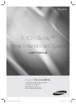
4.11.3 Model 3B PCI Backplane
Figure 4–17 Model 3B (10-Slot Legacy Backplane)
10-Slot PCI I/O Backplane
MR0260
66 MHz 3.3V Yes
66 MHz 3.3V Yes
33 MHz 5.0V Yes
33 MHz 5.0V Yes
33 MHz 5.0V Yes
33 MHz 5.0V Yes
33 MHz 5.0V Yes
Max
Speed Voltage Hot-Plug
33 MHz 5.0V No
33 MHz 5.0V No
33 MHz 5.0V No
SRM Console
Hose 2 Slot ID 1
Hose 2 Slot ID 2
Hose 0 Slot ID 11
Hose 3 Slot ID 2
Hose 3 Slot ID 1
Hose 0 Slot ID 10
Hose 1 Slot ID 2
Hose 1 Slot ID 1
Hose 0 Slot ID 9
Hose 0 Slot ID 8
Quick Reference
SRM Console to
Physical Slot Location
SRM Console
Hose 0 Slot ID 8
Slot ID 9
Slot ID 10
Slot ID 11
Hose 1 Slot ID 1
Slot ID 2
Hose 2 Slot ID 1
Slot ID 2
Hose 3 Slot ID 1
Slot ID 2
Physical Slot
10
9
6
3
8
7
1
2
5
4
1
2
3
4
5
7
8
9
10
6
The PCI slots are split across four independent 64-bit PCI buses, three buses at
33 MHz and one bus at 66 MHz. These buses correspond to Hose 0 through
Hose 3 in the system logical configuration.
Some PCI options require drivers to be installed and configured. These options
come with a floppy or a CD-ROM. Refer to the installation document that came
with the option and follow the manufacturer's instructions.
There is no direct correspondence between the physical numbers of the slots on
the I/O backplane and the logical slot identification reported with the SRM con-
sole show config command (described in Chapter 2). The table in Figure 4–17
maps the physical slot numbers to the SRM logical ID numbers for the back-
plane.
For information on restriction, see
http://www.compaq.com/alphaserver/
.
NOTE: To take advantage of 66 MHz, all modules in that hose must be 66 MHz
capable.
Содержание AlphaServer ES45 1B
Страница 4: ......
Страница 14: ...xiv 8 6 Electrical Characteristics All System Variants 8 7 8 7 Regulatory Approvals 8 9 8 8 Acoustic Data 8 10 ...
Страница 82: ......
Страница 110: ......
Страница 115: ...Configuring and Installing Components 4 5 Figure 4 2 Enclosure Panel Removal Pedestal 1 2 PK0234A 3 ...
Страница 119: ...Configuring and Installing Components 4 9 Figure 4 3 Removing Covers from a Tower PK0216A 5 4 3 1 2 2 2 2 1 1 ...
Страница 120: ...4 10 ES45 Owner s Guide Figure 4 4 Removing Covers from a Pedestal Rack PK0215A 1 1 4 5 3 2 2 2 1 2 ...
Страница 134: ...4 24 ES45 Owner s Guide Figure 4 10 Stacked and Unstacked DIMMs PK1209 Unstacked DIMMS Stacked DIMMS ...
Страница 138: ...4 28 ES45 Owner s Guide 4 10 Installing DIMMs Figure 4 13 Installing DIMMs Tower Pedestal Rack 2 1 1 1 1 1 1 PK0205B ...
Страница 149: ...Configuring and Installing Components 4 39 Figure 4 19 Installing a Hard Drive 3 4 2 1 MR0064 ...
Страница 159: ...Configuring and Installing Components 4 49 Figure 4 23 Disk Cage Installation PKO975 0B 7 8 3 6 ...
Страница 161: ...Configuring and Installing Components 4 51 Figure 4 24 Fan Locations 5 6 1 2 3 4 PK0208a ...
Страница 164: ......
Страница 238: ......
Страница 322: ......