INS_CNXE2GE2TX8MSPOE 11 Jan 2021 PAGE 29
INSTALLATION AND OPERATION MANUAL
CNXE2GE2TX8MSPOE
TECH SUPPORT: 1.888.678.9427
5.3.2 MSTI Mapping
The recovery time of STP and RSTP (seconds) may be unacceptable in some industrial
applications. MSTP technology supports multiple spanning trees within a network by grouping
and mapping multiple VLANs into different spanning-tree instances, known as MSTIs, to form
individual MST regions. Each switch is assigned to an MST region, consisting of one or more
MSTP switches with the same VLANs, at least one MST instance, and the same MST region name.
Switches can use different paths in the network to effectively balance loads.
This page allows you to examine and change the configurations of current MSTI ports. A MSTI
port is a virtual port, which is instantiated separately for each active CIST (physical) port for each
MSTI instance configured and applicable for the port. The MSTI instance must be selected before
MSTI port configuration options are displayed.
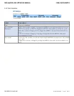
Label
Description
Configuration Name The name which identifies the VLAN to MSTI mapping. Bridges must share
the name and revision (see below), as well as the VLAN-to-MSTI mapping
configurations in order to share spanning trees for MSTIs (intra-region). The name
should not exceed 32 characters.
Configuration
Revision
Revision of the MSTI configuration named above. This must be an integer between
0 and 65535.
MSTI
The bridge instance. The CIST is not available for explicit mapping, as it will receive
the VLANs not explicitly mapped.
VLANS Mapped
The list of VLANs mapped to the MSTI. The VLANs must be separated with
commas and/or space. A VLAN can only be mapped to one MSTI. An unused MSTI
will be left empty (ex. without any mapped VLANs).


