background image

TECP-90-814 • Rev C • October 2020

Page 42

© 2020 

CommScope

. All Rights Reserved. 

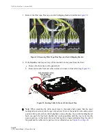
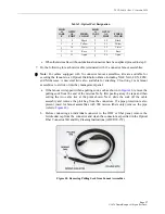
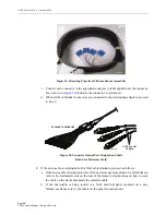
c. Connect the microcable MPO connector to the appropriate equipment MPO


connector. Labels are attached to each microcable, as shown in 

Figure 55

, that identify 

the cable number and the range of optical ports associated with the MPO connector. 

Figure 55. Cable Number and Optical Port Designation Labels

d. When all the microcable MPO connectors are connected to the equipment MPO


connectors, proceed to step 14. 

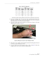
11. Complete the following for each stub end terminated with a non-functional connector: 

a. Record the label information (cable number, range of optical ports, and serial number) 

that is applied to each cable and then tag each cable so it can be identified when the 
cable jacket is removed for splicing. 

b. Cut off the non-functional connector and discard. 

c. Determine the point at which the microcable will be attached to the splice tray and 

then strip back the cable jacket to expose the optical fibers. 

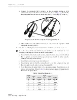
d. Splice the microcable optical fibers to the appropriate optical fibers following local 

policies and procedures. Refer to 

Table 3

 to determine the optical port designations for 

the microcable optical fibers. 

Note: 

Do not cut off the non-functional connector before cable installation has been 

completed or the integrity of the cable may be compromised.

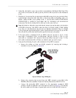
Table 3. Optical Port Designation

MICR

CABL

E

OPTIC

AL 

PORT

FIBER 

COLOR

MICR

CABL

E

OPTIC

AL 

PORT

FIBER 

COLOR

1

1

Blue

2

13

Blue

1

2

Orange

2

14

Orange

1

3

Green

2

15

Green

1

4

Brown

2

16

Brown

1

5

Slate

2

17

Slate

1

6

White

2

18

White

1

1 - 12

13 - 24

2

24155-B

1

1 - 12

13 - 24

2

CABLE

NUMBER

PORT

DESIGNATION

LABELS

Содержание Rapid Fiber 1RU

Страница 1: ... PANEL WITHOUT EXTERNAL SPOOL 12 5 1 Mounting the Panel on the Equipment Rack 13 5 2 Removing the Latch Shipping Bracket 15 5 3 Unwinding Microcable from Internal Cable Spool Tray 17 6 INSTALLING A RAPID FIBER PANEL WITH EXTERNAL SPOOL 23 6 1 Mounting the Panel Shell on the Equipment Rack 24 6 2 Unwinding Microcable from the External Spool 26 6 3 Mounting the RapidReel Cable Spool Tray in the Pane...

Страница 2: ...Rapid Fiber Panel has a RapidReel fiber cable spool tray It is available with singlemode RBR multimode OM4 plenum rated or indoor outdoor I O cable Panels with a cable length exceeding the capacity of the RapidReel cable spool tray have an external spool as well This manual describes how to install and operate this product Revision History Trademark Information CommScope CommScope logo Rapid Fiber...

Страница 3: ...or multi mode indoor plenum rated cable or indoor outdoor cable The spooled cable is preterminated to the bulkhead on the rear side Danger Danger is used to indicate the presence of a hazard that will cause severe personal injury death or substantial property damage if the hazard is not avoided Warning Warning is used to indicate the presence of a hazard that can cause severe personal injury death...

Страница 4: ...her 24 fiber module s with single mode LC UPC or APC or multimode LC UPC or 12 fiber module s with single mode SC UPC or APC or multimode SC UPC Breakout 12 fibers 2 mm or 900 micron in diameter up to nine feet 2 74 m in length terminated with 12 individual connectors These will be single mode SC UPC or APC single mode LC UPC or APC multimode SC UPC or multimode LC UPC connectors The 1RU Rapid Fib...

Страница 5: ...from the front or rear side as shown in Figure 3 After the cable spool tray is installed a lock on the tray holds the adapter bulkhead in a fixed position with the adapters facing toward the front When the lock is retracted the microcable is easily unwound by pulling it out of the spool The adapter bulkhead rotates with the tray to prevent the cable from twisting Excess microcable slack remains on...

Страница 6: ...Ground Connection Provides a point for securing a two hole lug used for connecting a grounding cable to the side of the enclosure Mounting Brackets Secure the panel to the equipment rack Two sets of mounting brackets are provided one set for 19 inch racks and one set for 23 inch racks The mounting brackets may be installed to provide a 2 4 or 5 inch recess Note When mounting multiple Rapid Fiber P...

Страница 7: ...enum cable or two 12 fiber I O cables When the spool is unwound the cables are routed to an ODF or fiber panel Excess slack may be wound back onto the spool Adapter Bulkhead Provides a point for connecting the equipment patch cords to the cable assemblies Front Port Designation Plate Identifies the optical port numbers on the adapter bulkhead The designation plate must be removed before the cables...

Страница 8: ... or multimode LC UPC The NG4access cabled modules will be either one 24 fiber LC module UPC or APC or two 12 fiber SC modules UPC or APC The MPO connectors are of 12 fiber construction and equipped with a pulling eye for use in paying out the cable The stub end non functional connectors are of similar construction and appearance as MPO connectors and also equipped with pulling eyes only the connec...

Страница 9: ... 3 Specifications and Dimensions Table 1 lists specifications Figure 7 shows dimensions for the 1RU Rapid Fiber Panel Table 1 Rapid Fiber Panel Specifications PARAMETER SPECIFICATION REMARKS Mechanical Dimensions HxWxD 1 72 x 17 42 x 14 73 in 4 4 x 44 24 x 37 4 cm Mounting rack 19 inch or 23 inch EIA or WECO Recess options 2 4 or 5 inches 5 08 10 16 or 12 7 cm Weight 14 lb 6 35 kg Fully loaded two...

Страница 10: ...um MPO receptor single mode SC UPC or APC single mode LC UPC or APC multimode SC or LC UPC NG4access LC cabled module one 24 fiber LC UPC or APC or two 12 fiber SC UPC or APC Environmental Operating conditions 23 F to 131 F 5 C to 55 C 5 to 85 RH No condensation Storage conditions 40 F to 158 F 40 C to 70 C 10 to 95 RH No condensation Table 1 Rapid Fiber Panel Specifications PARAMETER SPECIFICATIO...

Страница 11: ...s are used to connect the Rapid Fiber Panel to the active equipment Figure 8 Typical Rapid Fiber Panel Application 2 UNPACKING AND INSPECTION Use the following procedure to unpack and inspect the product 1 Before installing the product open the shipping carton s and carefully unpack the contents 2 Check the panel for damages or missing ship along parts per the list provided in Section 3 If there a...

Страница 12: ...R PANEL WITHOUT EXTERNAL SPOOL There are three main activities involved in installing a Rapid Fiber Panel without an external spool mounting the panel on an equipment rack removing the latch shipping brackets and unwinding the RapidReel cable spool tray This section provides a procedure for each of these activities Note The Rapid Fiber Panel is designed to be installed in an environmentally contro...

Страница 13: ...9 inch brackets at the required recess position as shown in Figure 9 4 Secure the panel to the rack or cabinet using the four 12 24 screws and 12 24 lock washers provided as shown in Figure 10 5 Connect a grounding wire to the panel in either of the two locations shown in Figure 11 on Page 14 using the two 10 32 screws and star washers provided A two hole grounding lug not provided but shown here ...

Страница 14: ...7 6 CM OF CLEARANCE AT THE REAR SIDE OF THE PANEL TO ALLOW THE SPOOL TO ROTATE FREELY AS THE CABLE IS UNWOUND 3 INCHES 12 24 SCREW AND LOCK WASHER 4 PLACES 26146 A 26145 A 10 32 SCREWS TIGHTEN SECURELY STAR WASHERS FRONT GROUNDING LOCATION REAR GROUNDING LOCATION NOTE FRONT GROUNDING IS NOT AVAILABLE WHEN THE MOUNTING BRACKETS ARE INSTALLED IN THE 2 INCH RECESS POSITION ...

Страница 15: ...sing the following procedure 1 Remove the fiber tape from the front center of the panel as shown in Figure 12 Figure 12 Removing Fiber Tape from Latch Shipping Bracket 2 Pull out the cable spool tray 1 and remove the blue tape 2 as shown in Figure 13 Figure 13 Pulling Out Tray 1 and Removing Blue Tape 2 26174 A FIBER TAPE 26175 A LATCH SHIPPING BRACKET 1 2 BLUE TAPE ...

Страница 16: ...igure 14 Figure 14 Locking Tray Into Payout Position 4 Slide the latch shipping bracket out of the cable spool tray as shown in Figure 15 and clear it from the panel then push the red latch and tray in to operational position Figure 15 Removing Latch Shipping Bracket from Tray Caution When removing shipping bracket use caution to avoid damaging fibers 26176 A LATCH SHIPPING BRACKET 26177 A LATCH S...

Страница 17: ...en the Rapid Fiber Panel front cover to provide clearance for the spool to rotate 2 Pull the red latch out to release the tray as shown in Figure 16 Figure 16 Pulling Red Latch Out to Release Tray 3 While holding the red latch out push the tray back slightly Continue pushing until the tray locks into the payout position as shown in Figure 17 Figure 17 Locking Tray Into Payout Position 26147 A RED ...

Страница 18: ... cable causing the internal spool and attached bulkhead panel to rotate Note Provide at least 3 inches 7 6 cm of clearance on the rear side of the panel to allow the spool to rotate freely as the microcable is unwound Caution If the cable fails to unwind check for obstacles or obstructions that would prevent the spool from turning The maximum recommended pull force that may be applied to the MPO c...

Страница 19: ...ng b Remove the microcable from the rear cable retainer and then push the connectors back into the space between the left side of the panel and the bulkhead panel This will form a slack loop at the front of the panel c Pull on the slack loop to draw the connectors through to the front NOTE TOP REMOVED TO SHOW CABLE SPOOL TRAY AND MICRO CABLE ROUTING DETAIL 26150 A STEP b PUSH MICROCABLE INTO CHASS...

Страница 20: ...e tabs shown in Figure 22 on both side of the panel on the rear side pull the spool tray out from the rear of the panel Figure 22 Pressing In Release Tabs To Withdraw Spool Tray c Remove the microcable from the cable retainer at the rear side of the spool tray and route the cable to the front as shown in Figure 23 Note There is a cable retainer on each corner of the panel Any of the cable retainer...

Страница 21: ...gn the cable spool tray with the mounting slot as shown in Figure 24 and carefully slide the spool tray into the mounting slot until the stop is reached f Press the black release tabs on both sides of the panel as shown in Figure 24 and then continue sliding the RapidReel cable spool tray into the mounting slot until it locks into place Note Be sure the microcable is pulled snug around the spool t...

Страница 22: ...t where the microcable exits the panel as shown in Figure 25 Figure 25 Placing Microcables Within Cable Retainer 10 Using the red latch rotate the tray clockwise and pull the tray forward to the locked operation position as shown in Figure 26 Figure 26 Pulling Tray Forward to Locked Operation Position 11 If routing the microcable through a trough or conduit proceed to Topic 7 on Page 34 for guidel...

Страница 23: ...s installed in the equipment rack or cabinet Topic 6 1 on Page 24 The microcable is unwound from the external spool Topic 6 2 on Page 26 The RapidReel cable spool tray is mounted within the panel shell Topic 6 3 on Page 27 The remaining microcable is unwound from the RapidReel cable spool tray Topic 6 4 on Page 30 Note The Rapid Fiber Panel is designed to be installed in an environmentally control...

Страница 24: ...8 3 If the panel shell is being installed in a 23 inch rack or cabinet in other than the 5 inch recess position remove the 23 inch mounting brackets and re install them at the required 2 or 4 inch recess position as shown in Figure 9 4 If the panel shell is being installed in a 19 inch rack or cabinet remove the 23 inch mounting brackets and install 23 inch brackets at the required recess 2 4 or 5...

Страница 25: ...vided but shown here for reference is recommended for the connection Figure 30 Grounding Rapid Fiber Panel Note Ground the unit to the local facility CBN Common Bonding Network or IBN Isolated Bonding Network per local practice 3 INCHES 12 24 SCREW AND LOCK WASHER 4 PLACES 26158 A 26159 A 10 32 SCREWS TIGHTEN SECURELY STAR WASHERS FRONT GROUNDING LOCATION REAR GROUNDING LOCATION NOTE FRONT GROUNDI...

Страница 26: ...ol Placed on Carousel 3 When the microcable has been completely unwound from the external spool STOP ROTATING THE SPOOL Note If the microcable will exit the panel from the rear place the spool at the rear side of the rack If the microcable will exit the panel from the front place the spool at the front side of the rack Note The external spool with attached RapidReel cable spool tray is pre mounted...

Страница 27: ...ed in the panel shell The cable spool tray may be installed in the panel shell from either the front or rear side Use the following procedure 1 Use a box cutter to open the box on top of the external spool as shown in Figure 32 Figure 32 Opening Box on Top of External Spool 2 Open the box as shown in Figure 33 Remove the cable spool tray and place the discarded external spool and box in the approp...

Страница 28: ...ray spool Note When mounting the cable spool trays in the panel shell ensure that the spool locking tabs are retracted in the pay out position To move the panel into the cable payout position first pull out the red latch slightly to release the tray then while holding the red latch out push the tray back slightly and continue pushing until the tray locks into the payout position At this point the ...

Страница 29: ...eel cable spool tray into the mounting slot until it locks into place 7 Locate the two 4 40 bonding screws that are sent separately with the ship along parts 8 Install the two 4 40 screws on either side of the panel at the points indicated in Figure 38 Tighten to 6 inch lbs 0 7 Newton meters of torque Figure 37 Pressing Black Release Tabs NOTE IF THE MICROCABLE ROUTES FROM THE FRONT INSERT THE CAB...

Страница 30: ...Use the following procedure to unwind the microcable on the RapidReel cable spool tray 1 Open the Rapid Fiber Panel front cover 2 Pull the red latch out to release the tray as shown in Figure 39 Figure 39 Pulling Red Latch Out to Release Tray 4 40 SCREW 26162 A SEE DETAIL A INSTALL SCREWS ON BOTH SIDES OF PANEL TIGHTEN TO 6 INCH LBS 0 7 Nm OF TORQUE DETAIL A 26147 A RED LATCH ...

Страница 31: ...push the tray back slightly Continue pushing until the tray locks into position as shown in Figure 40 Figure 40 Pushing the Tray Back In Slightly 4 Remove the blue tape that secures the cable to the right rear of the panel as shown in Figure 41 Figure 41 Removing Blue Tape 26148 A RED LATCH 26149 A BLUE TAPE ...

Страница 32: ...nel as shown in Figure 43 Note Provide at least 3 inches 7 6 cm of clearance on the rear side of the panel to allow the spool to rotate freely as the microcable is unwound Caution If the cable fails to unwind check for obstacles or obstructions that would prevent the spool from turning The maximum recommended pull force that may be applied to the MPO connector pulling eye fanout assembly pulling s...

Страница 33: ...he slack on the spool b Rotate the tray clockwise and pull the tray forward to the locked operation position as shown in Figure 44 Figure 44 Pulling Tray Forward to Locked Operation Position 8 Locate and install the front port designation plate as shown in Figure 45 Slide in the designation plate until it reaches the detents and snaps into place 26155 A REAR CABLE RETAINERS FRONT CABLE RETAINERS F...

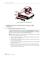
Страница 34: ...rough system Dress and secure microcable as specified by local practice Note Due to space constraints in conduit only cables with MPO connectors or MPO like non functional connectors should be routed through conduit Note This procedure begins at the point where the RapidReel cable spool tray or external spool is released and ready to be pulled as described in either Topic 5 2 on Page 15 or Topic 6...

Страница 35: ...led module proceed to step 8 5 Complete the following for each cable terminated with an MPO connector a Remove the pulling eye from each MPO connector by inserting and twisting a screwdriver or coin as shown in Figure 46 Figure 46 Removing a Pulling Eye b Remove the connector dust cap and clean the MPO connector as specified in the Multifiber Push On Assembly Connector Cleaning Instructions ADCP 9...

Страница 36: ...t at which the microcable will be attached to the splice tray and then strip back the cable jacket to expose the optical fibers d Splice the microcable optical fibers to the appropriate optical fibers following local policies and procedures Refer to Table 2 to determine the optical port designations for the microcable optical fibers Note Do not cut off the non functional connector before cable ins...

Страница 37: ...ly remove the pipe refer to Figure 49 b Before connecting an individual connector to the ODF or fiber panel remove the ferrule dust cap from the connector and clean the connector as specified in the Optical Fiber Connector Wet and Dry Cleaning Instructions ADCP 90 159 Figure 48 Removing Pulling Sock from Fanout Assemblies 1 8 Black 2 20 Black 1 9 Yellow 2 21 Yellow 1 10 Violet 2 22 Violet 1 11 Ros...

Страница 38: ...50 Connector Optical Port Designation Labels Shown for Reference Only 8 If the microcable is terminated with a NG4 cabled module proceed as follows a If the microcable is being routed to a NG4 universal panel mounted on a QNG4 frame refer to the laminated cards on the rear of the frame for instructions on how to route the cable on the frame and install the cabled module b If the microcable is bein...

Страница 39: ...snag on anything 10 Using the red latch rotate the tray clockwise and pull the tray forward to the locked operation position as shown in Figure 51 Figure 51 Pulling Tray Forward to Locked Operation Position 11 Locate and install the front port designation plate as shown in Figure 52 Slide in the designation plate until it reaches the detents and snaps into place Figure 52 Installing Front Port Des...

Страница 40: ...tape around the pulling swivel mesh and the trailing connector as shown in Figure 54 Figure 53 Inserting Microcable Lead Connector into Pulling Eye Figure 54 Wrap Pulling Swivel and Connectors with Vinyl Tape Note Due to space constraints in conduit only cables with MPO connectors or MPO like non functional connectors should be routed through conduit Note The swivel will ensure that proper pulling...

Страница 41: ...nd twisting a screwdriver or coin as shown in Figure 46 on Page 35 b Remove the connector dust cap and clean the MPO connector as specified in the Multifiber Push On Assembly Connector Cleaning Instructions ADCP 96 150 Caution Avoid using excessive force when unwinding microcable from the internal spool If the cable fails to unwind check for obstacles or obstructions that would prevent the spool f...

Страница 42: ...ntified when the cable jacket is removed for splicing b Cut off the non functional connector and discard c Determine the point at which the microcable will be attached to the splice tray and then strip back the cable jacket to expose the optical fibers d Splice the microcable optical fibers to the appropriate optical fibers following local policies and procedures Refer to Table 3 to determine the ...

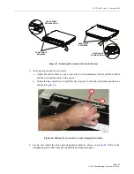
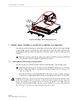
Страница 43: ...rward to the locked operation position as shown in Figure 56 Figure 56 Pulling Tray Forward to Locked Operation Position 14 When done be sure to pull the center red latch forward to first locking position This will lock the tray to prevent further spool rotation 15 Locate and install the front port designation plate as shown in Figure 57 Slide in the designation plate until it reaches the detents ...

Страница 44: ... 1 Using the red latch carefully pull the adapter bulkhead forward until the stop position is reached See Figure 58 and Figure 59 2 Locate the optical connector that requires cleaning and carefully disconnect it from the rear side of the bulkhead adapter 3 Clean the connector as described in the Optical Fiber Connector Wet and Dry Cleaning Instructions ADCP 90 159 4 Reinsert optical connector into...

Страница 45: ...2 Panel Cable Spool Tray and Microcable Serial Number Labels A superlabel that provides the product catalog number part number revision and date code is attached to the panel In addition a serial number label is attached to both the RapidReel cable spool tray and the microcables The locations of the various labels are shown in Figure 60 26147 A RED LATCH ...

Страница 46: ...the patch cords from the center of the panel outward to either side of the panel as shown in Figure 61 or to one side as shown in Figure 62 Danger Infrared radiation is invisible and can seriously damage the retina of the eye Do not look into the ends of any optical fiber Do not look directly into an optical adapter Exposure to invisible laser radiation may result An optical power meter should be ...

Страница 47: ...e Spool Tray Positions and How to Use Them The cable spool tray has three positions operation home cable payout inward and full connector access outward The panel ships in the operation position with the spool locking tab protruding through the right side of the panel shell as shown in Figure 63 26166 A PATCHCORDS CAN BE ROUTED EITHER UP OR DOWN CABLE RETAINER CABLE RETAINER 26167 A PATCHCORDS CAN...

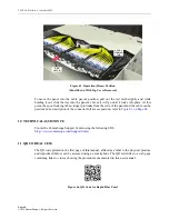
Страница 48: ... panel and the cable can be paid out For a description of the connector full access position refer to Topic 8 1 on Page 44 10 TECHNICALASSISTANCE Contact he CommScope Support Center using the following URL htt p www commscope com SupportCenter 11 QR CODE ACCESS The QR code printed on the first page of this manual affixed as a label to the physical product and reproduced below can be accessed using...

Отзывы: