CommScope OneCell Скачать руководство пользователя страница 80

Chapter 5

RP5100r installation 

OneCell

® 

 Hardware Installation, Release 4.5

5-8

DR

AF

T

4

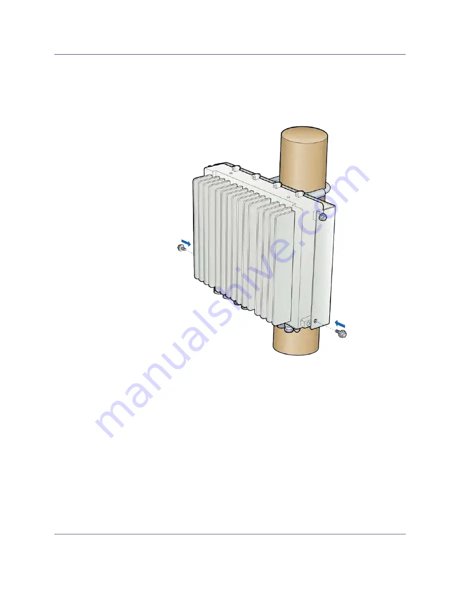
Align holes at bottom location of bracket. Insert and tighten the bottom screws 

through the plate hole into both sides of the RP. Be sure that all four screws are 

tightened. 

NOTE:  

The torque requirement for the mounting screws is 20-21 in-lbs. 

Содержание OneCell

Страница 1: ...DRAFT Hardware Installation Guide Release 4 5 Document Number M0303A2 OneCell Document Revision 4 5 01 Date September 2020 ...

Страница 2: ...MENTS INFORMATION AND RECOMMENDATIONS IN THIS MANUAL ARE BELIEVED TO BE ACCURATE BUT ARE PRESENTED WITHOUT WARRANTY OF ANY KIND EXPRESS OR IMPLIED USERS MUST TAKE FULL RESPONSIBILITY FOR THEIR APPLICATION OF ANY PRODUCTS THE SOFTWARE LICENSE AND LIMITED WARRANTY FOR THE ACCOMPANYING PRODUCT ARE SET FORTH IN THE INFORMATION PACKET THAT SHIPPED WITH THE PRODUCT AND ARE INCORPORATED HEREIN BY REFEREN...

Страница 3: ... 1 2 CommScope OneCell system 1 2 OneCell hardware components 1 3 Baseband Controller physical ports 1 3 Chapter 2 Preparing to install the OneCell system Overview 2 2 Before installing the OneCell components 2 2 Commissioning the OneCell network 2 2 PART 2 ONECELL COMPONENT INSTALLATION Chapter 3 Baseband Controller installation Preparing for Baseband Controller installation 3 2 Installing the Ba...

Страница 4: ...stallation 5 10 Chapter 6 RP2000 Installation Indoor Radio Point RP2000 installation overview 6 2 Ceiling mount 6 3 Mounting the Radio Point on the ceiling tile 6 5 Mounting the Radio Point above the ceiling tile 6 13 Flown mount 6 17 Flown mount installation 6 18 Pole mount 6 23 Pole mount installation 6 23 Chapter 7 RP2100 Installation Rugged Radio Point RP2100 installation overview 7 2 Pole mou...

Страница 5: ...ules D 2 Prerequisites D 2 Off site activities D 3 On site activities D 7 Post Install Verification D 11 Replacing Radio Points prerequisites and on site activities D 13 Prerequisites D 13 On site activities D 14 Replacing RP5100 series Radio Points D 16 Replacing a ceiling RP5100i above tile D 17 Replacing a flown mounted RP5100i D 32 Replacing a pole mounted RP5100i D 42 Replacing RP5100i RF mod...

Страница 6: ...on and power separation guidelines Overview E 2 Cable handling E 2 Cable termination E 3 Cable splicing E 4 Cable termination E 5 Cable grounding E 10 Lightning protection E 12 Important guidelines E 12 Indoor box E 12 Outdoor protection E 13 Ceiling connector E 15 Patch panel E 17 Power separation guidelines E 17 ...

Страница 7: ...Contents OneCell Hardware Installation Release 4 5 vii DRAFT ...

Страница 8: ...re provided by the systems integrator 5 3 Figure 5 3 RJ45 IP67 connector assembly 5 4 Figure 6 1 CommScope ceiling mount kit contents 6 3 Figure 6 2 Drop rail system integrator provided 6 4 Figure 6 3 CommScope supplied kit contents 6 17 Figure 6 4 Mounting bracket kit contents 6 23 Figure E 1 Unreel cable E 2 Figure E 2 Cable with sock attached using tie wrap E 3 Figure E 3 RJ45 IP67 connector E ...

Страница 9: ...seband Controller physical port assignments 1 4 Table A 1 RF exposure for OneCell at maximum power internal antennas for RP5000 series A 3 Table A 2 RF exposure for OneCell at maximum power internal antennas for RP2000 series A 4 Table C 1 Environmental and Physical specifications C 2 Table E 1 CAT 6A protection equipment parts list E 13 ...

Страница 10: ...List of tables x M0303A2 4 5 01 September 2020 DRAFT ...

Страница 11: ...evision history The following section lists documentation changes in OneCell Installation Guide v4 5 M0303A2 Revision 4 5 01 September 14 2020 Initial document release Added Band 5 RPM A5A11 B05 and Band 30 RPM A5A11 B30 RF exposure data to Table A 1 on page A 3 ...

Страница 12: ...Document revision history xii M0303A2 4 5 01 September 2020 DRAFT ...

Страница 13: ...hitects and business planners who are responsible for the planning and design of the CommScope OneCell deployment environment Purpose This guide provides the information necessary for installing the OneCell hardware in the operator s network What you need to know The reader should have a basic understanding of Data networks LTE technology General telecommunications practices Customer documentation...

Страница 14: ...sign in building systems Contains best practices for deployment including when to use clustering and how to manage capacity OneCell Installation Guide v4 5 M0303A2 Includes detailed installation instructions for Baseband Controller and Radio Points hardware OM and KPI Reference for OneCell Devices v4 5 M0303A3 Describes the operational measurements and key performance indicators for OneCell device...

Страница 15: ...an be used For example channel included yes no A valid command is channel included yes Font usage Bold input font Indicates text that must be entered exactly as shown For example Enter ping 192 23 10 12 Italic input font Indicates a variable parameter for which you must provide an actual value For example authentication key aukey aukey is a variable parameter A valid command is authentication key ...

Страница 16: ...f performed incorrectly can harm you Plain italic font Indicates file names directory paths book titles chapter titles and user accounts Bold font Indicates text that appears on screen exactly as shown for example names of screens names of buttons items on menus and items on pull down lists blue text Indicates a hypertext link Other conventions Indicates graphical user interface GUI menu path For ...

Страница 17: ...DRAFT Part I Overview and preparation Chapter 1 CommScope OneCell overview Chapter 2 Preparing to install the OneCell system ...

Страница 18: ...DRAFT ...

Страница 19: ... DRAFT Chapter 1 CommScope OneCell overview This chapter contains a high level overview of the OneCell deployment and the OneCell components installed in the OneCell system Overview 1 2 CommScope OneCell system 1 2 OneCell hardware components 1 3 ...

Страница 20: ... flexibility to neutralize macro interference in co channel small cell deployments It can be used to deliver unprecedented levels of capacity to hot spot areas by deploying radio points with overlapping coverage and enabling multi user MIMO In addition to these important benefits in user experience and data capacity OneCell provides superior economics and investment protection ease of deployment s...

Страница 21: ...nts Baseband Controller Baseband Controller Chassis Baseband Controller Module Power Fan Unit PFU Baseband Controller physical ports The following ports are on the front panel of the Baseband Controller Module Table 1 1 shows the port assignments In addition there is a connector used for the GPS antenna cable NOTE For more detailed BC port information see OneCell Network Planning Guide v4 5 M0303A...

Страница 22: ...nal via dual media port 8 IPsec 1 Gbps Dual Media RJ45 or SFP Backhaul Traffic S1 and OAM Interfaces via dual media port VLAN tags are configurable in Dual IPsec mode to separate different traffic streams on the same port 9 X2 and Redundancy 1 Gbps Dual Media RJ45 or SFP Fronthaul Traffic for X2 and Redundancy Cluster data via dual media port 10 RP Management and Timing 1 Gbps Dual Media RJ45 or S...

Страница 23: ...Chapter 1 CommScope OneCell overview OneCell Hardware Installation Release 4 5 1 5 DRAFT Figure 1 2 Baseband Controller ports Copper wire ports Fiber optic ports ...

Страница 24: ...Chapter 1 CommScope OneCell overview 1 6 M0303A2 4 5 01 September 2020 DRAFT ...

Страница 25: ...stallation Release 4 5 2 1 DRAFT Chapter 2 Preparing to install the OneCell system This section has the steps to complete before starting the OneCell installation Overview 2 2 Before installing the OneCell components 2 2 ...

Страница 26: ...OneCell components the system integrator must plan the network for the topology that will be deployed See OneCell Network Planning Guide 913023 CommScope recommends that cables and switches be in place before installing the OneCell components See Appendix E Cable installation and power separation guidelines for more information Commissioning the OneCell network To bring your OneCell system up you ...

Страница 27: ...T Part II OneCell component installation Chapter 3 Baseband Controller installation Chapter 4 RP5100i installation Chapter 5 RP5100r installation Chapter 6 RP2000 Installation Chapter 7 RP2100 Installation ...

Страница 28: ...DRAFT ...

Страница 29: ...and Controller installation procedures including chassis installation into a rack Baseband Controller Module and Power Fan Unit installation into the Baseband Controller Chassis and the cables required for a basic installation Preparing for Baseband Controller installation 3 2 Installing the Baseband Controller into a rack 3 2 ...

Страница 30: ... need a coaxial cable with an SMA type male connector to the Baseband Controller For information on RF gain requirements see OneCell Network Planning Guide v4 5 M0303A1 Installing the Baseband Controller into a rack The Baseband Controller can be installed in a 19 inch or 600mm rack The Baseband Controller Chassis package contains two kits one with 19 inch brackets and one with 600mm brackets CAUT...

Страница 31: ...band Controller installation OneCell Hardware Installation Release 4 5 3 3 DRAFT 2 Slide the chassis into the rack 3 Line up the holes in the chassis ears to the holes in the rack 4 Secure the chassis with the screws ...

Страница 32: ...Chapter 3 Baseband Controller installation 3 4 M0303A2 4 5 01 September 2020 DRAFT 5 Carefully slide the BC into the front of the chassis 6 Secure the BC by tightening the front panel screws ...

Страница 33: ...the back of the rack carefully slide the PFU into the back of the chassis CAUTION The PFU has a fan hazard A label is affixed to the top of the PFU indicating the hazard NOTE The connectors on the PFU should fit easily into the connector on the BC Do not force the PFU into the chassis Fan hazard label ...

Страница 34: ...Chapter 3 Baseband Controller installation 3 6 M0303A2 4 5 01 September 2020 DRAFT 8 Secure the PFU by tightening the thumb screws 9 Connect the power cord to the PFU ...

Страница 35: ...ntroller installation OneCell Hardware Installation Release 4 5 3 7 DRAFT 10 On the Baseband Controller Module s front panel connect the GPS antenna cable 11 Connect the Ethernet or fiber optic cable to the appropriate port ...

Страница 36: ...2020 DRAFT 12 On the back of the Baseband Controller turn on the power The LEDs on the front panel will be solid green when the power is on If none are on check your power connection If the LED pattern is other than all green see Baseband Controller LED patterns on page B 2 ...

Страница 37: ...RAFT Chapter 4 RP5100i installation This chapter describes installing indoor Radio Points on ceiling tiles above ceiling tiles on poles and in a flown configuration RP5100i installation overview 4 2 Ceiling mount 4 3 Flown mount 4 22 Pole mount 4 31 ...

Страница 38: ...the ceiling type Ceiling mount on tile Ceiling mount above tile Flown mount Pole mount NOTE Once the Radio Point is installed and powered on it may take up to 20 minutes for the frequency to stabilize and lock NOTE If the MR port is connected to a switch that does not provide IEEE802 3bt type 4 PoE power the SR port can be used to provide power with a PoE injector For more information see OneCell ...

Страница 39: ...nt RP above or on the ceiling tile requires the following hardware provided by CommScope Radio Point plate and screws 4 octagon box 1 1 2 deep with 1 2 side cutouts Clamp and screw Figure 4 1 CommScope ceiling mount kit contents Octagon box Mounting plate for octagon box with 2 screws Mounting plate for RP with 4 screws ...

Страница 40: ...nt RP above or on the ceiling tile requires the following hardware provided by the system integrator Drop rail Eaton B line BA50A or equivalent with a static load capacity of at least 25 lbs without a drop wire recommended Figure 4 2 Drop rail system integrator provided Drop rail Clamp 2 screws ...

Страница 41: ...FT Mounting the Radio Point on the ceiling tile 1 Remove two ceiling tiles from the overhead 2 Place the octagon box on the tile and trace the outline Cut the opening 3 Drill a 1 2 inch diameter hole for the Ethernet cable pass through NOTE Use a 1 1 2 deep RACO 8125 or equivalent ...

Страница 42: ...apter 4 RP5100i installation 4 6 M0303A2 4 5 01 September 2020 DRAFT 4 Attach the octagon box to the ceiling bracket using a clamp and screw 70 mm 2 7 138 mm 5 4 Octagon box Screws Drop ceiling rail Clamp ...

Страница 43: ...Chapter 4 RP5100i installation OneCell Hardware Installation Release 4 5 4 7 DRAFT 5 Replace the ceiling tile with the cutouts ...

Страница 44: ...Chapter 4 RP5100i installation 4 8 M0303A2 4 5 01 September 2020 DRAFT 6 Install the drop rail octagon box assembly over the modified tile ...

Страница 45: ...0i installation OneCell Hardware Installation Release 4 5 4 9 DRAFT 7 Attach the mounting plate onto the octagon box and feed the Ethernet cable through the small hole in the ceiling tile Ethernet cable Mounting plate ...

Страница 46: ...stallation 4 10 M0303A2 4 5 01 September 2020 DRAFT 8 Attach base plate to the Radio Point NOTE Apply thread locking compound to screws prior to installation 9 Mount the Radio Point on the octagon box plate Ethernet cable ...

Страница 47: ...Chapter 4 RP5100i installation OneCell Hardware Installation Release 4 5 4 11 DRAFT 10 Secure Radio Point to the octagon plate ...

Страница 48: ...Chapter 4 RP5100i installation 4 12 M0303A2 4 5 01 September 2020 DRAFT 11 Remove the cover from the RP NOTE The cover is attached to the RP with two lanyards ...

Страница 49: ...Chapter 4 RP5100i installation OneCell Hardware Installation Release 4 5 4 13 DRAFT 12 Connect Ethernet cable to the MR port on the Radio Point ...

Страница 50: ...Chapter 4 RP5100i installation 4 14 M0303A2 4 5 01 September 2020 DRAFT 13 Replace plastic cover on the Radio Point 14 Replace the ceiling tile next to the Radio Point ...

Страница 51: ...Chapter 4 RP5100i installation OneCell Hardware Installation Release 4 5 4 15 DRAFT Mounting the Radio Point above the ceiling tile 1 Remove ceiling tile from the overhead ...

Страница 52: ...er 4 RP5100i installation 4 16 M0303A2 4 5 01 September 2020 DRAFT 2 Attach the octagon box to the bracket NOTE CommScope recommends an Eaton B line BA50A adjustable bracket Clamp Drop rail Octagon box Screw ...

Страница 53: ...allation OneCell Hardware Installation Release 4 5 4 17 DRAFT 3 Attach the bracket to the mounting plate to the octagon box 4 Attach plate to the Radio Point NOTE Apply thread locking compound to screws prior to installation ...

Страница 54: ...Chapter 4 RP5100i installation 4 18 M0303A2 4 5 01 September 2020 DRAFT 5 Attach the Radio Point to the octagon box mounting plate ...

Страница 55: ...Chapter 4 RP5100i installation OneCell Hardware Installation Release 4 5 4 19 DRAFT 6 Install drop rail above the ceiling tile ...

Страница 56: ...r 4 RP5100i installation 4 20 M0303A2 4 5 01 September 2020 DRAFT 7 Remove the cover from the RP NOTE The cover is attached to the RP with two lanyards 8 Connect the Ethernet cables to the Radio Point MR port ...

Страница 57: ...Chapter 4 RP5100i installation OneCell Hardware Installation Release 4 5 4 21 DRAFT 9 Replace the cover on the Radio Point NOTE The minimum clearance for cooling is 3 inches Ceiling tile 3 ...

Страница 58: ...nfiguration is used for building where there are no drop ceilings Mounting the Radio Point RP in the flown configuration requires the following hardware provided by CommScope in the mounting kit Radio Point plate and screws 4 octagon box 1 1 2 deep with 1 2 side cutouts NOTE Remove the top middle cutout Clamp and screw this hardware is not required for the flown mount option ...

Страница 59: ...mScope flown mount kit contents Mounting the Radio Point RP in the flown configuration requires the following hardware provided by the system integrator Rod 3 8 inch threaded Nut Lock nut nylon Flat washers Octagon box Mounting plate for octagon box with 2 screws Mounting plate for RP with 4 screws ...

Страница 60: ...inch rod cut to the required length to the ceiling 2 Install the nut and a flat washer on the rod 3 Slide the octagon box on the rod and install a flat washer and the nylon lock nut NOTE Be sure the bracket is tight between the nuts and there is enough clearance at the end of the rod to attach the bracket to the Radio Point ...

Страница 61: ...Chapter 4 RP5100i installation OneCell Hardware Installation Release 4 5 4 25 DRAFT 4 Attach plate to octagon box ...

Страница 62: ...Chapter 4 RP5100i installation 4 26 M0303A2 4 5 01 September 2020 DRAFT 5 Attach the mounting plate to the Radio Point ...

Страница 63: ...Chapter 4 RP5100i installation OneCell Hardware Installation Release 4 5 4 27 DRAFT 6 Attach the Radio Point to the octagon box ...

Страница 64: ...Chapter 4 RP5100i installation 4 28 M0303A2 4 5 01 September 2020 DRAFT 7 Remove the cover from the RP NOTE The cover is attached to the RP with two lanyards ...

Страница 65: ...Chapter 4 RP5100i installation OneCell Hardware Installation Release 4 5 4 29 DRAFT 8 Connect the Ethernet cable to the Radio Point MR port ...

Страница 66: ...Chapter 4 RP5100i installation 4 30 M0303A2 4 5 01 September 2020 DRAFT 9 Attach the plastic cover to the Radio Point Installation is complete ...

Страница 67: ... the Radio Point RP on a pole requires the following hardware provided by CommScope in the mounting kit Mounting bracket Screws Figure 4 4 Mounting bracket kit contents Mounting the Radio Point RP on a pole requires the following hardware provided by the system integrator Adjustable clamp at least 2 inches larger than the circumference of the pole Pole mount installation 1 Attach the bracket to th...

Страница 68: ...tallation 4 32 M0303A2 4 5 01 September 2020 DRAFT 2 Slide the adjustable clamp through the slots on the Radio Point bracket 3 Wrap the clamp around the pole and tighten the clamp screw to secure the Radio Point to the pole ...

Страница 69: ...Chapter 4 RP5100i installation OneCell Hardware Installation Release 4 5 4 33 DRAFT 4 Remove the cover from the RP NOTE The cover is attached to the RP with two lanyards ...

Страница 70: ...Chapter 4 RP5100i installation 4 34 M0303A2 4 5 01 September 2020 DRAFT 5 Connect the Ethernet cable to the Radio Point MR port ...

Страница 71: ...Chapter 4 RP5100i installation OneCell Hardware Installation Release 4 5 4 35 DRAFT 6 Replace the plastic cover on the Radio Point ...

Страница 72: ...Chapter 4 RP5100i installation 4 36 M0303A2 4 5 01 September 2020 DRAFT Installation is complete ...

Страница 73: ...n Release 4 5 5 1 DRAFT Chapter 5 RP5100r installation This chapter describes installing Rugged Radio Points on poles and walls Rugged Radio Point installation overview 5 2 Pole mount installation 5 4 Wall mount installation 5 10 ...

Страница 74: ...P ships with the following hardware Radio Point Mounting plate Mounting bolts M8 Hex RJ45 IP67 connector for CAT 6A cables Figure 5 1 Hardware provided by CommScope NOTE An M8 hex wrench is required to install mounting bolts Mounting the Radio Point RP on a pole requires the following hardware provided by the system integrator Two U bolts Four nuts ...

Страница 75: ...ector https www conec com catalog en rj45 stecker set html to connect the RJ45 to the SR port For more information see OneCell Network Planning Guide v4 5 M0303A1 Figure 5 2 Hardware provided by the systems integrator Mounting the Radio Point RP on a wall requires the following hardware provided by the system integrator Four molly screws capable 50 lb 23 kg minimum rating NOTE Once the Radio Point...

Страница 76: ...3 RJ45 IP67 connector assembly Pole mount installation There is vertical orientation for pole mount installations NOTE The minimum pole diameter requirement is 4 102mm Vertical pole mount 1 Slide the two U bolt clamps onto the pole and secure the RP mounting plate to the clamps with four nuts ...

Страница 77: ...Chapter 5 RP5100r installation 5 5 M0303A2 4 5 01 September 2020 DRAFT ...

Страница 78: ... 5 RP5100r installation OneCell Hardware Installation Release 4 5 5 6 DRAFT 2 Insert two screws into the upper holes on opposite sides of the RP Required orientation is with connectors at the bottom of the RP ...

Страница 79: ... 5 01 September 2020 DRAFT 3 Hang the RP to the mounting bracket using the installed screws CAUTION Ensure that the RP is oriented correctly with all connectors at the bottom of the RP Required orientation with connectors at the bottom of the RP ...

Страница 80: ...Release 4 5 5 8 DRAFT 4 Align holes at bottom location of bracket Insert and tighten the bottom screws through the plate hole into both sides of the RP Be sure that all four screws are tightened NOTE The torque requirement for the mounting screws is 20 21 in lbs ...

Страница 81: ...pter 5 RP5100r installation 5 9 M0303A2 4 5 01 September 2020 DRAFT 5 Connect the antenna cables on the bottom of the RP 6 Connect the Ethernet cable RJ45 end to the bottom of the RP to the MR port MR port ...

Страница 82: ...installation 5 10 M0303A2 4 5 01 September 2020 DRAFT Wall mount installation 1 Drill four holes in the wall using the mounting plate to determine the hole locations Mount the backplate on the wall with four molly screws ...

Страница 83: ...allation OneCell Hardware Installation Release 4 5 5 11 DRAFT 2 Insert two screws into the upper holes on opposite sides of the RP as shown in the drawing below Required orientation is with connectors at the bottom of the RP ...

Страница 84: ...20 DRAFT 3 Attach the RP to the mounting plate 4 Tighten the top screws on the RP and insert and tighten the bottom screws on the RP NOTE The torque requirement for the mounting screws is 20 21 in lbs Required orientation is with connectors at the bottom of the RP ...

Страница 85: ...Chapter 5 RP5100r installation OneCell Hardware Installation Release 4 5 5 13 DRAFT 5 Insert and tighten the bottom screws through the plate hole into both sides of the RP ...

Страница 86: ...ber 2020 DRAFT 6 Connect the antenna cables on the bottom of the RP 7 Connect the Ethernet cable RJ45 end to the bottom of the RP to the MR port NOTE Insert the Ethernet surge protection as required by local code for example DTK MRJPOEX or DTK MRJPOES MR port ...

Страница 87: ...ter 6 RP2000 Installation This chapter describes installing indoor Radio Points on ceiling tiles above ceiling tiles on poles and in a flown configuration Indoor Radio Point RP2000 installation overview 6 2 Ceiling mount 6 3 Flown mount 6 17 Pole mount 6 23 ...

Страница 88: ...n overview There are four configurations for installing the Radio Point which are dependent on the ceiling type Ceiling mount on tile Ceiling mount above tile Flown mount Pole mount NOTE Once the Radio Point is installed and the powered on it may take up to 20 minutes for the frequency to stabilize and lock ...

Страница 89: ...ing hardware provided by CommScope Radio Point mounting plate and 4 screws Octagon box mounting plate and 2 screws 4 octagon box 1 1 2 deep with 1 2 side cutouts Clamp with screw not required for flown mount option Figure 6 1 CommScope ceiling mount kit contents Octagon box Clamp with 1 screw Mounting plate for octagon box with 2 screws Mounting plate for RP with 4 screws ...

Страница 90: ...2 4 5 01 September 2020 DRAFT Mounting the Radio Point RP above or on the ceiling tile requires the following hardware provided by the systems integrator Drop rail Eaton B line BA50 recommended Figure 6 2 Drop rail system integrator provided ...

Страница 91: ...llation OneCell Hardware Installation Release 4 5 6 5 DRAFT Mounting the Radio Point on the ceiling tile 1 Remove two ceiling tiles from the overhead 2 Place the octagon box on the tile and trace the outline Cut the opening ...

Страница 92: ...le for the Ethernet cable pass through NOTE Use a 1 1 2 deep RACO 8125 or equivalent 4 Attach the octagon box to the ceiling bracket using a clamp and screw NOTE CommScope recommends the Eaton B line BA50 bracket Hole for mounting plate 1 2 inch diameter hole Octagon box Screw Drop ceiling rail Clamp ...

Страница 93: ...Chapter 6 RP2000 Installation OneCell Hardware Installation Release 4 5 6 7 DRAFT 5 Replace the ceiling tile with the cutouts ...

Страница 94: ...Chapter 6 RP2000 Installation 6 8 M0303A2 4 5 01 September 2020 DRAFT 6 Install the drop rail assembly over the ceiling tile with the cutouts ...

Страница 95: ...eCell Hardware Installation Release 4 5 6 9 DRAFT 7 Attach the mounting plate onto the octagon box 8 Attach base plate to the Radio Point NOTE Apply thread locking compound to screws prior to installation Ethernet cable Mounting plate ...

Страница 96: ...Chapter 6 RP2000 Installation 6 10 M0303A2 4 5 01 September 2020 DRAFT 9 Mount the Radio Point to the octagon box plate 10 Secure the Radio Point ...

Страница 97: ...Chapter 6 RP2000 Installation OneCell Hardware Installation Release 4 5 6 11 DRAFT 11 Connect the Ethernet cable to the Radio Point 12 Replace the second ceiling tile ...

Страница 98: ...Chapter 6 RP2000 Installation 6 12 M0303A2 4 5 01 September 2020 DRAFT Installation is complete ...

Страница 99: ...tion OneCell Hardware Installation Release 4 5 6 13 DRAFT Mounting the Radio Point above the ceiling tile 1 Remove ceiling tile from the overhead 2 Attach the octagon box to the bracket Screw Octagon box Drop ceiling rail Clamp ...

Страница 100: ...000 Installation 6 14 M0303A2 4 5 01 September 2020 DRAFT 3 Attach the mounting plate to the Radio Point NOTE Apply thread locking compound to screws prior to installation 4 Attach the Radio Point to the octagon box ...

Страница 101: ...apter 6 RP2000 Installation OneCell Hardware Installation Release 4 5 6 15 DRAFT 5 Install the drop rail assembly to the ceiling tile rail NOTE The minimum clearance for cooling is 3 inches Ceiling tile 3 ...

Страница 102: ...Chapter 6 RP2000 Installation 6 16 M0303A2 4 5 01 September 2020 DRAFT 6 Connect Ethernet cable to RP 7 Replace the ceiling tile ...

Страница 103: ...ere there are no drop ceilings Mounting the Radio Point RP in the flown configuration requires the hardware listed in Indoor Radio Point RP2000 installation overview on page 6 2 Figure 6 3 CommScope supplied kit contents Mounting the Radio Point RP in the flown configuration requires the following hardware provided by the system integrator Rod 3 8 inch threaded 2 flat washers Nut Lock nut nylon ...

Страница 104: ...ptember 2020 DRAFT Flown mount installation 1 Attach the threaded 3 8 inch rod cut to the required length to the ceiling 2 Install the nut and a flat washer on the rod 3 Slide the octagon box onto the rod and install a flat washer and the nylon lock nut ...

Страница 105: ... RP2000 Installation OneCell Hardware Installation Release 4 5 6 19 DRAFT 4 Attach the plate with two screws to the octagon box 5 Attach the CommScope supplied mounting plate to the Radio Point with four screws ...

Страница 106: ...Chapter 6 RP2000 Installation 6 20 M0303A2 4 5 01 September 2020 DRAFT 6 Attach the Radio Point to the octagon box ...

Страница 107: ...Chapter 6 RP2000 Installation OneCell Hardware Installation Release 4 5 6 21 DRAFT 7 Secure the Radio Point to the octagon box plate ...

Страница 108: ...Chapter 6 RP2000 Installation 6 22 M0303A2 4 5 01 September 2020 DRAFT 8 Connect the Ethernet cable to the Radio Point Installation is complete ...

Страница 109: ... Point RP on a pole requires the following hardware provided by CommScope in the mounting kit Mounting bracket 4 screws Figure 6 4 Mounting bracket kit contents Mounting the Radio Point RP on a pole requires the following hardware provided by the system integrator Adjustable clamp at least 2 inches larger than the circumference of the pole Pole mount installation 1 Attach the bracket to the Radio ...

Страница 110: ...5 01 September 2020 DRAFT 2 Slide the adjustable clamp through the slots on the Radio Point bracket 3 Wrap the clamp around the pole and tighten the clamp screw to secure the Radio Point to the pole 4 Connect the Ethernet cable to the Radio Point ...

Страница 111: ...Chapter 6 RP2000 Installation OneCell Hardware Installation Release 4 5 6 25 DRAFT Installation is complete ...

Страница 112: ...Chapter 6 RP2000 Installation 6 26 M0303A2 4 5 01 September 2020 DRAFT ...

Страница 113: ...elease 4 5 7 1 DRAFT Chapter 7 RP2100 Installation This chapter describes installing Rugged Radio Points on poles and walls Rugged Radio Point RP2100 installation overview 7 2 Pole mount installation 7 4 Wall mount installation 7 17 ...

Страница 114: ...io Point Mounting plate Mounting brackets Four tamper resistant mounting screws M5 RJ45 IP67 connector Two 4 3 10 antenna couplers NOTE A tamper resistant T25 Torx bit 1 4 hex shank attached to a driver handle is required to secure the tamper resistant mounting screws Mounting the Radio Point RP on a pole requires the following hardware provided by the system integrator Two adjustable clamps ...

Страница 115: ...provided by the system integrator Four molly screws capable 50 lb 23 kg minimum rating Before installing the RP on the pole terminate the RP end of the Ethernet cable with the RJ45 IP67 connector provided in the box NOTE Once the Radio Point is installed and the powered on it may take up to 20 minutes for the frequency to stabilize and lock ...

Страница 116: ...ertical pole mount Horizontal pole mount NOTE The minimum pole diameter requirement is 4 102mm Vertical pole mount 1 Attach mounting brackets to mounting plate NOTE The torque requirement for the bracket mounting screws is 5 6 in lbs 2 Slide the adjustable clamp through the slots on each RP mounting bracket on the RP plate Slide adjustable clamp end through slots ...

Страница 117: ...Chapter 7 RP2100 Installation 7 5 M0303A2 4 5 01 September 2020 DRAFT 3 Wrap each clamp around the pole and tighten the clamp screw to secure the RP to the pole ...

Страница 118: ...allation Release 4 5 7 6 DRAFT 4 Insert two screws into the upper holes on opposite sides of the RP as shown in the drawing below CAUTION Ensure that the RP is oriented correctly with the two antenna connectors at the top of the RP Required orientation ...

Страница 119: ...Chapter 7 RP2100 Installation 7 7 M0303A2 4 5 01 September 2020 DRAFT 5 Hang the RP to the mounting bracket using the installed screws Align holes at bottom location of bracket ...

Страница 120: ...ardware Installation Release 4 5 7 8 DRAFT 6 Insert and tighten the bottom screws through the plate hole into both sides of the RP Be sure that all four screws are tightened NOTE The torque requirement for the mounting screws is 20 21 in lbs ...

Страница 121: ... M0303A2 4 5 01 September 2020 DRAFT 7 Connect the antenna couplers on the top of the RP NOTE Check the antenna coupler manufacturer s documentation for torque requirements 8 Connect the Ethernet cable RJ45 end to the bottom of the RP ...

Страница 122: ...er 7 RP2100 Installation 7 10 M0303A2 4 5 01 September 2020 DRAFT Horizontal pole mount 1 Attach mounting brackets to mounting plate NOTE The torque requirement for the bracket mounting screws is 5 6 in lbs ...

Страница 123: ...r 7 RP2100 Installation OneCell Hardware Installation Release 4 5 7 11 DRAFT 2 Slide the adjustable clamp through the slots on each RP mounting bracket on the RP plate Slide adjustable clamp end through slots ...

Страница 124: ... 7 12 M0303A2 4 5 01 September 2020 DRAFT 3 Wrap each clamp around the pole and tighten the clamp screw to secure the RP to the pole 4 Insert two screws into the upper holes on opposite sides of the RP as shown in the drawing below ...

Страница 125: ...apter 7 RP2100 Installation OneCell Hardware Installation Release 4 5 7 13 DRAFT CAUTION Ensure that the RP is oriented correctly with the two antenna connectors at the top of the RP Required orientation ...

Страница 126: ...er 7 RP2100 Installation 7 14 M0303A2 4 5 01 September 2020 DRAFT 5 Hang the RP to the mounting bracket using the installed screws Align holes at bottom location of bracket and install two additional screws ...

Страница 127: ...rdware Installation Release 4 5 7 15 DRAFT 6 Insert and tighten the bottom screws through the plate hole into both sides of the RP Be sure that all four screws are tightened NOTE The torque requirement for the mounting screws is 20 21 in lbs ...

Страница 128: ...6 M0303A2 4 5 01 September 2020 DRAFT 7 Connect the antenna couplers on the top of the RP NOTE Check the antenna coupler manufacturer s documentation for torque requirements 8 Connect the Ethernet cable RJ45 end to the bottom of the RP ...

Страница 129: ...ation OneCell Hardware Installation Release 4 5 7 17 DRAFT Wall mount installation 1 Drill four holes in the wall using the mounting plate to determine the hole locations Mount the backplate on the wall with four molly screws ...

Страница 130: ...Chapter 7 RP2100 Installation 7 18 M0303A2 4 5 01 September 2020 DRAFT 2 Insert two screws into the upper holes on opposite sides of the RP as shown in the drawing below Required orientation ...

Страница 131: ...ll Hardware Installation Release 4 5 7 19 DRAFT 3 Attach the RP to the mounting plate Tighten the top screws on the RP and insert and tighten the bottom screws on the RP NOTE The torque requirement for the mounting screws is 20 21 in lbs ...

Страница 132: ...rt and tighten the bottom screws through the plate hole into both sides of the RP 5 Connect the antenna couplers on the top of the RP NOTE Check the antenna coupler manufacturer s documentation for torque requirements 6 Connect the Ethernet cable RJ45 end to the bottom of the RP ...

Отзывы: