background image

CommScope Era

 High Power Carrier Access Point Installation Guide — Preliminary

M0201AKB_uc

Page 34

© January 2019 CommScope, Inc.

 Installing a CAP H


Connect the Antenna Cable

The following information regarding antenna mapping and is relevant to all CAP H variants. 

For Non-MIMO bands, there is no channel mapping option for the transceiver/antenna port. The 
transceiver/antenna port relationship is fixed in hardware.

For MIMO bands, the Era GUI maps MIMO channels according to their AP designation:

AP0 to antenna port ANT1 

AP1 to antenna port ANT2. 

When using SISO channels on a CAP H that supports MIMO, the system will automatically balance the 
number of channels between the two antenna ports, where the first SISO channel is mapped to ANT1, the 
second SISO channel is mapped to ANT2, and so on.

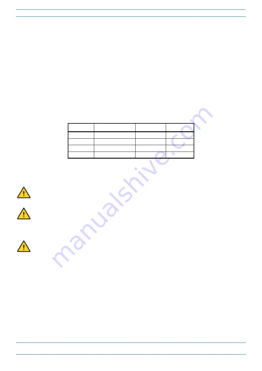
Use 

Table 9

 to determine how to connect to the antenna correctly for each CAP H variation.

Table 9. 

Mapping CAP H Models to Antennas

Part Number

Model Name

ANT or ANT 1

ANT 2

7772983-xxxx CAP H 8/9/18/21

8/9/18/21

Not Applicable

7821740-xxxx CAP H 9/18/21/26

9/18/21/26

Not Applicable

7825719-xxxx CAP H 7E/80-85/17E/19 7E/80-85/17E/19 Not Applicable

7825730-xxxx CAP H 17E/17E/19/19

17E/19 (MAIN)

17E/19 (MIMO)

When attaching the antenna cable connector, refer to the corresponding documentation of the connector 
manufacturer. The bending radius of the antenna cable must remain within the given specifications. Observe 
all cautions listed below.

Make sure that the fiber cable used meets the RF and environmental requirements for this installation.

Use an appropriate torque wrench for the 4.3-10 type connectors (5 N-m, 44 in lb) with 22mm (7/8) in 
opening.

Do NOT use your hands or any other tool (such as a pair of pliers). This might cause damage to the 
connector and lead to a malfunction of the CAP H.

To minimize passive inter-modulation (PIM) distortion, pay attention to the physical condition of the 
connector junctions:

Do not use connectors that show signs of corrosion on the metal surface.

Prevent the ingress of water or dirt into the connector.

Use protective caps for the connectors when not mounted.

Before mounting follow the steps in 

"Clean the RF Cable Connectors" on page 35

.

Attach and torque the connectors properly.

Avoid metallic abrasion when mounting the connectors by only screwing the connecting nut, but not 
turning the whole connector.

Use a torque wrench to fasten the connector, as described above.

Содержание Era M0201AKB_uc

Страница 1: ...CommScope Era High Power Carrier Access Point Installation Guide M0201AKB_uc January 2019 PRELIMINARY DRAFT ...

Страница 2: ...urbed conditions Should further information be desired or should particular problems arise which are not covered sufficiently for the purchaser s purposes contact CommScope CommScope reserves the right to change all hardware and software characteristics without notice COPYRIGHT 2019 CommScope Inc All Rights Reserved This document is protected by copyright No part of this document may be reproduced...

Страница 3: ...ectro Static Discharge 15 General Installation Safety Requirements 16 Compliance 16 Equipment Symbols Used Compliance 19 Required Antenna Distances 19 Installing a CAP H 20 CAP H Installation and Cascade Rules 20 Prepare for Installation 20 Recommended Tools and Material 21 Unpack and Inspect the CAP H and Optional Accessories 21 Installation Cautions 21 Determine the Mounting Site 23 Wall Mountin...

Страница 4: ...ntenance 48 Routine Maintenance of the CAP H 49 Replacing the Fan Unit 49 Cleaning the Heat Sink 52 Contacting CommScope 53 CMS Global Technical Support 53 Telephone Helplines 53 Online Support 53 Waste Electrical and Electronic Equipment Recycling 53 Hardware to Software Mapping Information 54 Mobility Solutions Technical Training 54 Accessing Era ION E Series User Documentation 55 ...

Страница 5: ...80 85 17E 19 North America 7825730 xxxx CAP H 17E 17E 19 19 North America 1 The xxxx suffix provides information as to whether the CAP H is AC or DC Contact your local sales representative for further information See also CommScope Part Numbers on page 3 For information on how to find the minimum software requirements for Era hardware refer to Hardware to Software Mapping Information on page 54 Do...

Страница 6: ...in a managed device destroy or corrupt information or interrupt or stop services The icon to the left indicates a caution or warning that pertains to laser equipment The icon to the left indicates a caution or warning that pertains to Radio Frequency RF The icon to the left indicates that the hardware is susceptible to Electro Static Discharge ESD damage The icon to the left indicates a caution or...

Страница 7: ...y Solutions OPT Optical Transport dB Decibel PA Power Amplifier dBm Decibel milliwatts PN Part Number DC Direct Current RAN Regional Area Network EFTA European Free Trade Association RF Radio Frequency EMC Electromagnetic Compatibility RU Rack Unit EMEA Europe Middle East Africa SFP Small Form Factor Pluggable EU European Union SISO Single Input Single Output F Fahrenheit SMF Single Mode Fiber FCC...

Страница 8: ...architecture in their hubs All operator Baseband signals analog BTS and BBU CPRI are supplied to the Switching CAN by the WINs so no RFD or CDD Cards can be installed in the Switching CAN The Switching CAN then combines the signals from all WINs and distributes those signals to the TENs and the TENs provide the signals to the APs APs are not directly connected to a Switching CAN Users have full an...

Страница 9: ...e CAP H converts data arriving at the CAP H to analog signals and sends them to the Antenna port On the uplink received signals are digitized and serialized into data streams which are sent back to the Classic CAN or TEN Figure 1 on page 5 shows how a CAP H can be deployed in an Era system e POI Classic CAN Node B TEN Fiber CAP H CAP H CAP H CAP H CAP H CAP H CAP H Cat6A Ethernet Figure 1 CAP H in...

Страница 10: ...Antenna Connectors on page 9 Connectors and Status LED on Models with One Antenna Figure 2 shows the connectors on an AC version of the CAP H that has one antenna connector Table 2 on page 7 maps the callouts in Figure 2 and Figure 3 on page 8 and describes the connectors and STATUS LED Figure 3 on page 8 shows the connectors on a DC version of the CAP H that has one antenna connector Do not remov...

Страница 11: ...OCTIS Kit PN 7770612 Optical Port 1 ships with a dust cap that can be discarded upon unit installation Connects a Secondary CAP H to Optical Port 2 of the Primary CAP H 3 2 Optical Port 2 Connects to an optional cascaded secondary CAP H via an Optical OCTIS Kit PN 7770612 Optical transport occurs over Single Mode Fiber SMF or Multi Mode Fiber MMF Optical Port 2 ships with factory installed EMI wea...

Страница 12: ...Scope Era High Power Carrier Access Point Installation Guide Preliminary M0201AKB_uc Page 8 January 2019 CommScope Inc CAP H Overview Figure 3 Location of Connectors and Status LED on DC Version with One Antenna Connector ...

Страница 13: ...ors on an AC version with two antenna connectors Table 3 on page 10 maps the callouts in Figure 4 and Figure 5 on page 11 and describes the connectors and STATUS LED Figure 5 on page 11 shows the connectors on a DC version with two antenna connectors Do not remove caps from any of the connectors until instructed to do so 1 2 3 4 6 7 5 9 8 Figure 4 Location of Connectors and Status LED on AC Versio...

Страница 14: ...n be discarded upon unit installation Connects a Secondary CAP H to Optical Port 2 of the Primary CAP H 3 2 Optical Port 2 Connects to an optional cascaded secondary CAP H via an Optical OCTIS Kit PN 7770612 Optical transport occurs over Single Mode Fiber SMF or Multi Mode Fiber MMF Optical Port 2 ships with factory installed EMI weatherproof plug and must remain plugged if not in use 4 STATUS Sta...

Страница 15: ...1AKB_uc CommScope Era High Power Carrier Access Point Installation Guide Preliminary January 2019 CommScope Inc Page 11 CAP H Overview Figure 5 Location of Connectors and Status LED on DC Version with Two Antenna Connectors ...

Страница 16: ...he mounting kit must be ordered separately it is not contained with the standard equipment Wall Mounting Kit CommScope Part Number 7661581 includes the following One Top Mounting Bracket One Bottom Mounting Bracket Four M8x25 screws Four split lock washers Four 8 4 mm flat washers Pole Mounting Kit CommScope Part Number 7661538 includes the following One Top Mounting Bracket with Screw Band One Bo...

Страница 17: ...ifies the OCTIS Kit options Table 4 CAP H OCTIS Kits Kit Name CommScope PN Description Optical OCTIS Kit 7770612 Use as follows Optical Port 1 to connect the CAP H to a Classic CAN or TEN Optical Port 2 to cascade a second CAP H Ships with the following grommets 6mm nominal diameter for use with cables with OD range from 4 8 5 8 7mm nominal diameter for use with cables with OD range from 5 8 6 8 8...

Страница 18: ...al current Obey all general and regional installation and safety regulations relating to work on high voltage installations as well as regulations covering correct use of tools and personal protective equipment Laser radiation Risk of eye injury in operation Do not stare into the laser beam do not view the laser beam directly or with optical instruments High frequency radiation in operation Risk o...

Страница 19: ...ny spare parts which are not sold or recommended by the manufacturer Due to power dissipation the CAP H may reach a very high temperature Ensure sufficient airflow for ventilation Do not operate this equipment on or close to flammable materials Use caution when servicing the CAP H Although the CAP H is internally protected against overvoltage it is strongly recommended to ground earth the antenna ...

Страница 20: ... P D where P mW is the radiated power at the antenna i e the max rated repeater output power in addition to the antenna gain minus the loss between the repeater and the antenna PD mW cm is the allowed Power Density limit acc to 47 CFR 1 1310 B for general population uncontrolled exposures which is f MHz 1500 for frequencies from 300MHz to 1500MHz 1 for frequencies from 1500MHz to 100 000MHz RF exp...

Страница 21: ...du dispositif Cet appareil est conforme avec Sante Canada Code de se curite 6 Le programme d installation de cet appareil doit s assurer que les rayonnements RF n est pas e mis au dela de I exigence de Sante Canada Les informations peuvent e tre obtenues http www hc sc gc ca ewh semt pubs radiation radio_guide lignes_direct eng php Les changements ou modifications non expresse ment approuve s par ...

Страница 22: ... reception which can be determined by turning the equipment off and on the user is encouraged to try to correct the interference by one or more of the following measures Reorient or relocate the receiving antenna Increase the separation between the equipment and receiver Connect the equipment into an outlet on a circuit different from that to which the receiver is connected Consult the dealer or a...

Страница 23: ... ISED licensee You MUST have an ISED LICENCE or the express consent of an ISED licensee to operate this device AVERTISSEMENT Ce produit N EST PAS un appareil de CONSOMMATION Il est conçu pour être installé par un installateur approuvé par un titulaire de licence d ISDE Pour utiliser cet appareil vous DEVEZ détenir une LICENCE d ISDE ou avoir obtenu le consentement exprès d un titulaire de licence ...

Страница 24: ...y CAP H is the Secondary CAP H To cascade two CAP Hs connect the fiber optic cable from Optical Port 2 of the Primary CAP H to Optical Port 1 of the Secondary CAP H You connect CAP Hs to an OPT Card in a Classic CAN or TEN Each OPT Card has four 10 Gbps ports labeled 1 4 for fiber connections The OPT Card can only be installed in Slots L1 L4 of a Classic CAN or TEN You can connect up to 4 CAP Hs p...

Страница 25: ...he commercial carrier and notify CommScope Technical Support see CMS Global Technical Support on page 53 Save the damaged cartons for inspection by the carrier 4 Save all shipping containers for use if the equipment requires shipment at a future date Installation Cautions Read and observe all cautions listed in Safely Working with a CAP H on page 14 Do not install the unit in a way or at a place w...

Страница 26: ...unit is required To ensure sufficient airflow when mounting the CAP H in enclosed spaces two lid openings one for the air inlet and the other for the air outlet must be provided Do not block these air inlets and outlets when mounting the CAP H The size of each opening must equal at least 18 x 18 cm 300 cm2 Ensure that there is no thermal short circuit between the air inlet and air outlet Make sure...

Страница 27: ...e weight of the external cables and connectors that the mounting site must be able to support Table 7 Maximum CAP H Installation Weights CAP H installed with this option Maximum Lift Weight Total Hanging Weight Mounting Kit Part Number kg lbs kg lbs Pole 7661538 29 63 93 31 68 3 Wall 7661581 29 63 93 31 68 3 Use the dimensions shown in Table 8 and Figure 6 on page 24 to determine the mounting site...

Страница 28: ... 9 3 11 12 13 14 16 17 17 18 20 19 21 CommScope Era High Power Carrier Access Point Installation Guide Preliminary M0201AKB_uc Page 24 January 2019 CommScope Inc Installing a CAP H Figure 6 Required Space to Mount a CAP H ...

Страница 29: ...the responsibility of the installer to verify that the supporting surface will safely support the combined load of the electronic equipment and all attached hardware and components and to ensure that the CAP H is safely and securely mounted 1 Mark the position of the drilling holes The following graphic shows the location of the mounting holes and the pitch of the CAP H during the mounting procedu...

Страница 30: ...ep 1 3 Insert dowels in each of the holes drilled in Step 2 The dowels are not included with the CAP H shipment as the suitable type depends on the wall material Dowels should be used for all wall mountings except for when mounting to a wooden wall 4 Mount the brackets A to the wall using the M8x20 screws B split lock washers C and flat washers D so that the flat washers are against the mounting b...

Страница 31: ...AP H 5 Do the following to mount the CAP H in the Wall Mount Bracket a Hang the CAP H in the upper bracket b Push the CAP H into to the lower bracket A and then fasten it to the lower bracket using two M8x20 screws B split lock washers C and flat washers D so that the flat washers are against the mounting bracket torque to 27 N m A B D C ...

Страница 32: ...the CAP H to a wall using the Pole Mounting Kit CommScope Part Number 7661538 It is the responsibility of the installer to verify that the pole will safely support the combined load of the electronic equipment and all attached hardware and components and to ensure that the CAP H is safely and securely mounted The maximum diameter of the pole or column cannot exceed 120 mm 4 7 inch Maximum of 120 m...

Страница 33: ...tion Guide Preliminary January 2019 CommScope Inc Page 29 Installing a CAP H 1 Mark the position of where the screw bands should be attached to the pole as shown in the following graphic which also shows the pole mounting pitches Minimum 775 mm 30 51 Maximum 788 mm 31 ...

Страница 34: ...ccess Point Installation Guide Preliminary M0201AKB_uc Page 30 January 2019 CommScope Inc Installing a CAP H 2 Use two screw bands B for the upper and one for the lower bracket to fasten the two brackets A to the pole as shown below A B ...

Страница 35: ...he threads of the band causing the band to tighten around the pole When fastening the brackets make sure that they are installed congruently and not at an angle to each other To determine the distance between the clamps refer to Step 1 on page 29 4 Do the following to mount the CAP H in the Pole Mount Bracket a Hang the CAP H in the upper bracket b Push the CAP H into to the lower bracket and then...

Страница 36: ... H Follow the procedures in the order in which they are given Ground the CAP H The CAP H must be grounded Do not use the grounding bolts to connect an external device 1 Connect an earth bonding cable to the grounding bolt connections on the outside of the CAP H chassis as shown in the graphic to the right AC versions will have one M8 bolt see Figure 2 on page 6 DC versions will have two M6 bolts s...

Страница 37: ...wo washers b Refasten all parts by tightening the hex nut c Connect the other end of the earth bonding cable to a suitable permanent ground Flat washers M8 Hex nut Contact washer Earth Bonding cable M8x30 set screw M8 Hex nut Locking ring Ground of a second unit in a cascade must be connected to the same equipotential bonding terminal as the Primary CAP H Use bonding cables of the same length as s...

Страница 38: ...0 85 17E 19 7E 80 85 17E 19 Not Applicable 7825730 xxxx CAP H 17E 17E 19 19 17E 19 MAIN 17E 19 MIMO When attaching the antenna cable connector refer to the corresponding documentation of the connector manufacturer The bending radius of the antenna cable must remain within the given specifications Observe all cautions listed below Make sure that the fiber cable used meets the RF and environmental r...

Страница 39: ...ainst injury from flying particles This procedure requires the use of flammable material There is a risk of fire Keep away from sources of ignition This procedure requires the use of eye irritant product There is a risk of eye irritation Avoid contact with eyes and skin Wear protective clothing especially protective glasses Do the following to clean the RF cable connectors 1 Gather the following c...

Страница 40: ...r winding 5 Use a cotton bud drenched with isopropyl alcohol to clean the lip of the inner ring 6 Use a cotton bud drenched with isopropyl alcohol to clean the inside surface of the inner ring 7 Use a cotton bud drenched with isopropyl alcohol to clean the inside of the center conductor spring tines 8 Remove the protective caps from the unit connector and then clean it the same way that you cleane...

Страница 41: ... the CAP H 9 Use compressed air to remove metal chips and small particles from the mating and inner surfaces of the connector 10 Use a lint free wipe drenched with isopropyl alcohol to clean the winding area 11 Use a cotton bud drenched with isopropyl alcohol to clean the inside mating surface of the inner ring 12 Use a cotton bud drenched with isopropyl alcohol to clean the outside surface of the...

Страница 42: ...s 4 Fasten the coupling nut hand tight Do not turn the connector but the coupling nut only 5 Retainthe cable connectorwiththecounterwrench A andfasten the coupling nut with the torque wrench B until the torque is applied torque wrench clicks Note that for angled antenna connectors you should use your hand to retain the cable connector and fasten the coupling nut with the torque wrench Make sure on...

Страница 43: ... 10GBase SRR Multi Mode OM3 300m OM4 400m 7680813 SFP 10GBase LR Single Mode 10km 7803247 SFP 10GBase CWDM 270 40km 7803249 SFP 10GBase CWDM 290 40km 7803291 SFP 10GBase CWDM 310 40km 7803293 SFP 10GBase CWDM 330 40km 7803295 SFP 10GBase CWDM 350 40km 7803298 SFP 10GBase CWDM 370 40km 7803900 SFP 10GBase CWDM 390 40km 7803902 SFP 10GBase CWDM 410 40km 7803904 SFP 10GBase CWDM 430 40km 7803906 SFP ...

Страница 44: ... Optical Port 2 d Clean the connectors on the SMF or MMF following the fiber supplier s recommendations e Install an SFP and Optical OCTIS Kit on the end of the fiber that will connect to the Primary CAP Hand connect that end of the SMF or MMF to the CAP H Optical Port 2 connector Note the maximum range listed in Table 10 See CAP H Connectors and Status LED on page 6 for the location of Optical Po...

Страница 45: ...e See Ground the CAP H on page 32 If the CAP H MAINS connector is not easily accessible a disconnect device in the mains power circuit must be provided within easy reach A connection of the mains supply to a power socket requires the power socket to be near the CAP H Before connecting or disconnecting the CAP H MAINS connector ensure that the mains power supply is disconnected Make sure that an ap...

Страница 46: ...H 9 18 21 26 3x1 5mm2 3 2 m 10 5 Protec ve cap Outer diameter of cable is 8 9mm MAINS Power Cable PN 7633458 01 ships with CAP H 7E 80 85 17E 19 and CAP H 17E 17E 19 19 3x16AWG 3 2 m 10 5 Protec ve cap Outer diameter of cable is 9 9mm Figure 7 MAINS Power Cable For the AC power supply connection a minimum cross section of 1 5 mm2 is required Each wire must observe the applicable national regulatio...

Страница 47: ...lectrical codes Allow enough slack in the cable at the CAP H to plug or unplug the cable into the CAP H MAINS connector 5 Wire the power cable to the junction box or receptacle Refer to the color code and pin numbers shown in Figure 7 on page 42 6 With the cable s MAINS plug disconnected from the CAP H turn the circuit breaker on unscrew the plug s protective cover and carefully test the plug with...

Страница 48: ... AC CAP H go to Connect the MAINS Power and Power on an AC CAP H on page 42 The MAINS cable must be properly secured observing local regulations and electrical codes Be sure to allow enough slack in the cable at the CAP H to mount or dismount the cable into the DC MAINS connector of the CAP H A CAP H requires M6 double lug DC cable connectors with stud holding spacing of 15 88 mm 5 8 as shown in F...

Страница 49: ...1 Unscrew the two M3 x 12 captive screws and take off the cover from the DC MAINS connector housing At the CAP H housing the cover is inserted into a recess so first lift the cover at the front and carefully pull it out from the recess 2 Remove the rubber plug Rubber plug M3 x 12 cap ve screw M3 x 12 cap ve screw 3 Install a conduit fitting not shipped with the CAP H to the 34 52 mm hole This must...

Страница 50: ...les are provided the distance between the threaded holes is 34 5 mm 1 36 A B C D 5 mm 2 A 34 5 mm 1 36 B 8 mm 32 D C 34 52 mm 1 36 O 5 Mount the housing cover by inserting it into the recess at the repeater cabinet and fastening the two M3 x 12 captive screws MAINS power must be interruptible with an external mains breaker 40 A For the MAINS breaker observe the local regulations of the DC provider...

Страница 51: ...s as soon as the Flash LED request is initiated in the GUI and remains active until the duration set in the Auto stop parameter has expired For further information refer to the Era configuration guide that corresponds to this installation see Accessing Era ION E Series User Documentation on page 55 Steady Orange The CAP H is not operational for one of the following reasons The CAP H is booting The...

Страница 52: ...d Safety Precautions on page 14 Property Damage Warnings on page 15 Guard Against Damage from Electro Static Discharge on page 15 General Installation Safety Requirements on page 16 Installation Cautions on page 21 The unit reaches high temperature in operation Risk of burns by hot surface Do not touch the unit before it has sufficiently cooled down Disconnect the CAP H from mains power before sta...

Страница 53: ...ain temperature threshold it will reduce output power If this doesn t help and the temperature continues to rise above 85 C 185 F the Power Amplifier PA will shut down Once temperature decreases the PA will automatically turn back on Rotating fans Risk of injury in operation Wear tight fitting clothes and disconnect mains before connecting or replacing or cleaning the Fan Unit The Fan Unit can onl...

Страница 54: ...ccess Point Installation Guide Preliminary M0201AKB_uc Page 50 January 2019 CommScope Inc Maintenance 4 Unscrew the four Pan head screws two at each side of the cabinet Pan Head screws two each side of the chassis 5 Remove the fan cover ...

Страница 55: ...sis c Pull the Fan Unit from the CAP H chassis Fan connector Pan Head screw Pan Head screw Pan Head screw Pan Head screw 7 Do the following to install the new Fan Unit a Insert the new Fan Unit into the CAP H chassis b Use the four Pan head screws that you removed in step Step 6 to secure the new Fan Unit to the CAP H chassis c Connect the fan connector d Replace the Fan Unit cover that was remove...

Страница 56: ...nk 1 Adhere to all cautions and warnings listed in Rules to Observe During Maintenance on page 48 and at the start of this section 2 Label any unlabeled cables before disconnecting them to ensure correct reconnection 3 Disconnect the CAP H from mains power and make sure it is powered down before proceeding 4 Follow Step 4 on page 50 through Step 6 on page 51 to remove the Fan Unit from the CAP H c...

Страница 57: ...24x7 Helpline Online Support To go to the CommScope Wireless Support Request web site from which you can initiate a Technical Support ticket do one of the following Scan the QR Code to the right If viewing this document online as a PDF click on the following URL link http www commscope com wisupport Enter the preceding URL into your web browser and then press ENTER on your keyboard Waste Electrica...

Страница 58: ...ted in separate course panels for further information on a course click its Full details button Instructor led courses are conducted in North America and Europe Before choosing a course please verify the region 3 To view the course schedule and register click Course Registration at the top of the course page this opens the Partner Learning Center Login page If you have an account enter your Userna...

Страница 59: ...ernatively you can go to the following web address to access the portal https www mycommscope com 2 Access to the Customer Portal requires a user account and password On the Sign In page do one of the following If you have an account enter your Email address and Password and then click Sign In If you don t have an account click New user registration and follow the prompts 3 Click DCCS to open the ...

Страница 60: ......

Отзывы: