
G
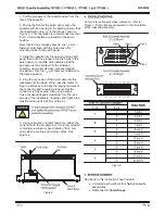
1. Pull the plungers of the cassette away from the
face of the cassette.
2. Facing the front of the patch panel, align the
cassette with an opening in the patch panel so that
the chamfered corner is on the left (as shown in
Figure 1). This orientation is recommended so that
Port 1 of all cassettes are located at the same
position.
Note that for the shielded cassette, the
1
/
4
–turn
fastener must align with the hole above the
mounting holes in the patch panel.
3. Slide the cassette into the opening of the patch
panel then push the plungers into the holes in the
patch panel. An audible click indicates that the
plungers are fully seated. For the shielded
cassette, using a small cross–recessed tipped
screwdriver, turn the
1
/
4
–turn fastener
clockwise to
the locked position.
4. Plug the connector of the trunk cable into the
receptacle (at the back) of the cassette. Refer to
Figure 2. Make sure to align the keying features of
the connector and receptacle. Ensure that the
connector is fully seated,
then using a small
cross–recessed tipped screwdriver, turn the jack
screws of the receptacle
clockwise and tighten to a
maximum torque of 0.23 Nm [2 lbf–in.].
5. Using cable ties or similar fasteners, attach the
trunk cable to the tie–down bar. It is recommended
to maintain a minimum bend radius of 50.8 mm
[2 in.] when securing and routing cables. See
Figure 2.
Figure 2
For port–to–cable pair cross–reference, refer to
Figure 3. Port numbers are based on the orientation
of the cassette assembly.
Figure 3
Revisions to this instruction sheet include:
Corrected part numbers for shielded cassette
assemblies
Rebranded to
CommScope