11
SET-UP & INSTALLATION (cont.)
Connecting Hose or Pipe to the Discharge Outlet
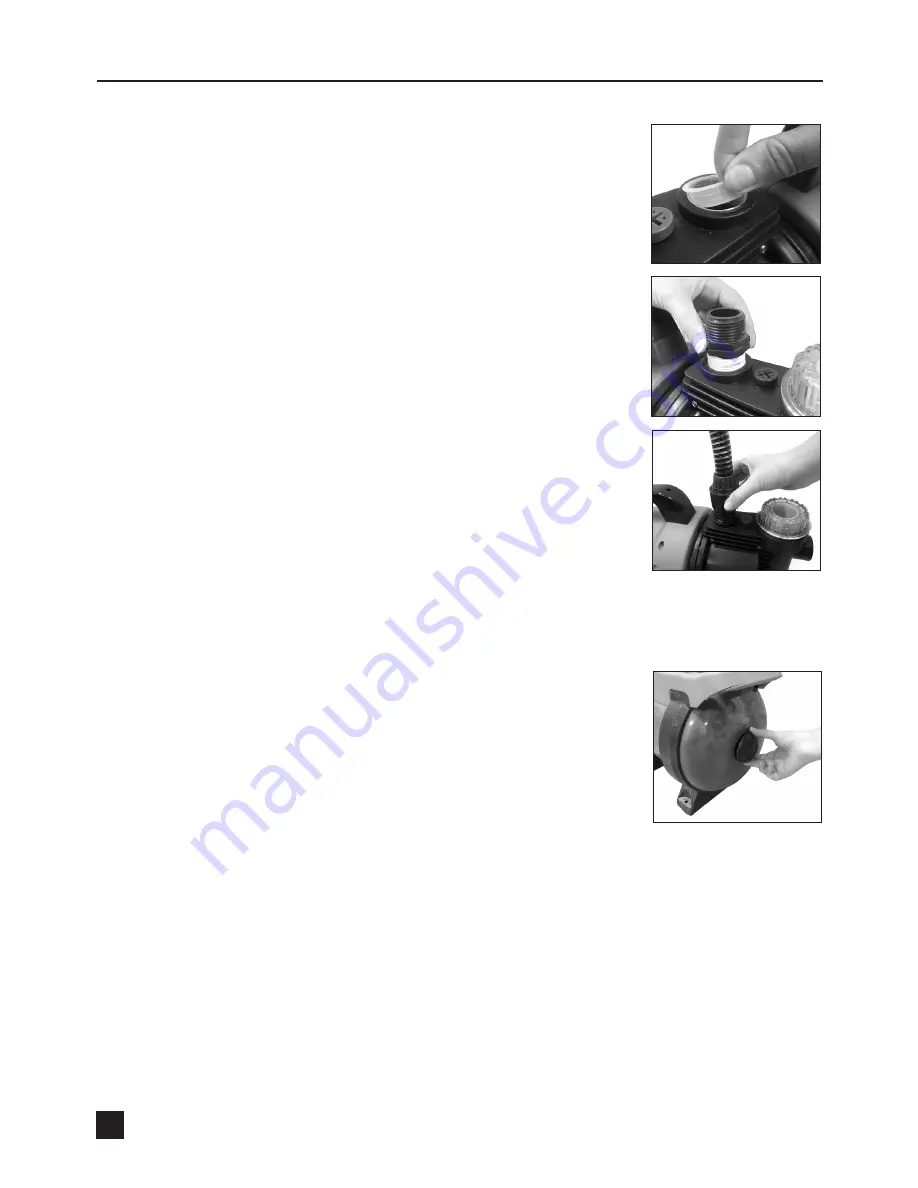
4. Remove the plastic protection cover from the discharge outlet (1) (Fig. 8).
Note:
Teflon tape (not included) is recommended on threads to ensure a
water tight seal and prevent any leakage.
5. Insert a 1’’ male threaded hose adaptor (not included) into the discharge
outlet (1) (Fig. 9).
6. Securely attach the output hose or pipe to the threaded insert (not
included) and other end of the discharge line (Fig. 10). Ensure you have
the correct diameter of the output hose or pipe that is compatible with
the water discharge application.
Note:
The output hose or pipe you are using must have a minimum
diameter of 19mm (
3
/
4
’’). A smaller diameter output hose or pipe will result in
a lower flow rate.
Note:
Ensure the output hose or pipe is not restricted in any way and no pressure is obstructing the
hose or pipe when the pump is in operation.
IMPORTANT:
Inside the pressure tank (6) is an expandable water bladder
and an air compartment, its maximum pressure should lie at approximately
1.3 bar (19 psi) when no water is in the tank. Pumping water into the water
bladder causes the bladder to expand so that the pressure in the air
compartment increases to switch-off level. If the air pressure is too low, you
should increase it. To do so, unscrew the air valve cover (12) from the end
of the pressure tank (6) (Fig. 11) and top up the pressure to the correct
level, approx. 1.3 bar (19 psi) using an air pump with a guage at the air
valve (13).
Fig. 8
Fig. 9
Fig. 10
Fig. 11


