6
•
•
Turning the power on
Connect 5.0V / 1A power adaptor to
⑧
DC adaptor input located on the side of WI-249LM.
Turn the
⑥
Power switch on located at the bottom of WI-249LM. At the right-lower side of FND
Display, a small dot LED is on to indicate the device is on.
•
•
Paring (Main / Sub devices)
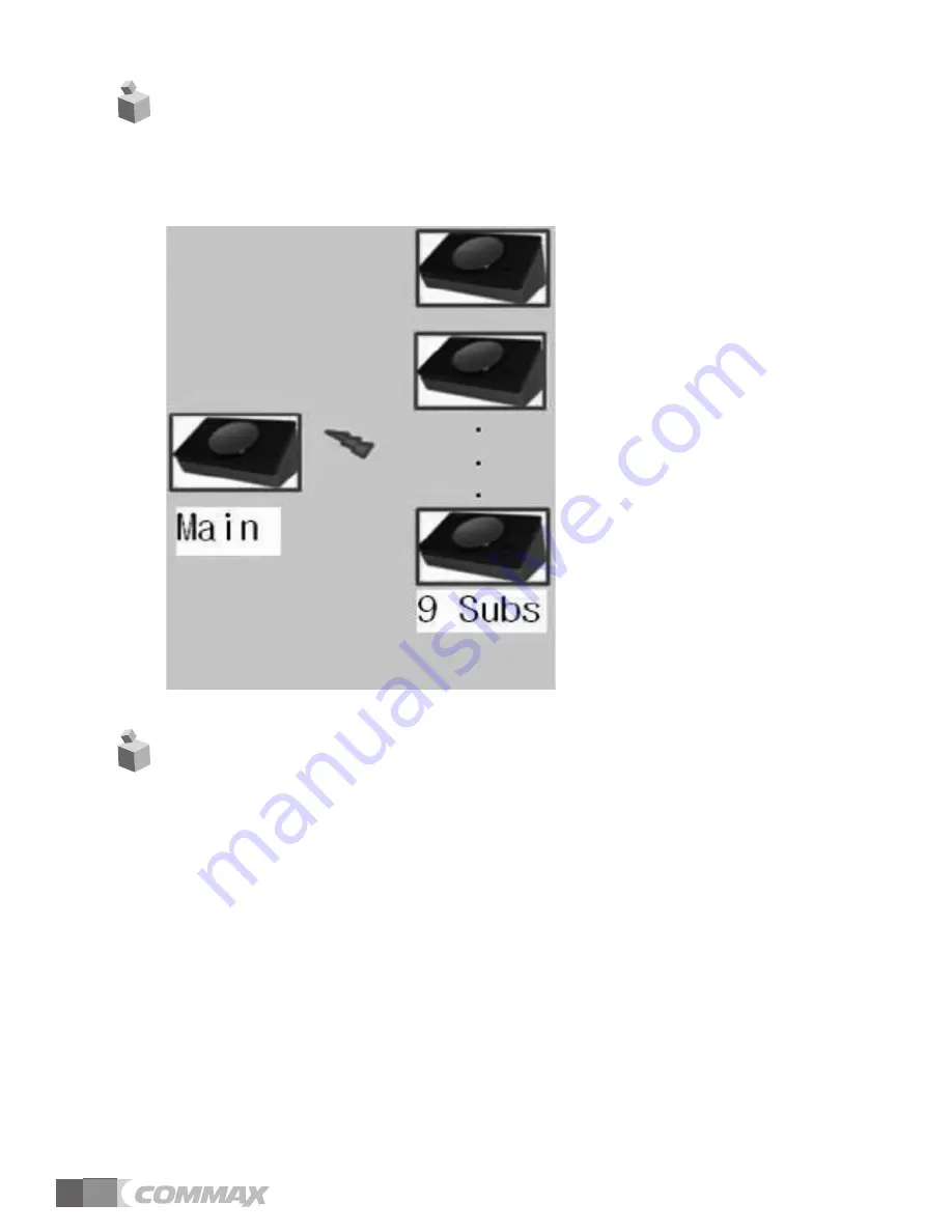
The main device allocates a number to each sub device from number ‘00’ to ‘99’ when pairing. For
example, if you would like to allocate the number ‘03’ to a WI-249LS, use the
⑤
Select button to
choose ‘03’ and press
⑦
Volume switch for 5 seconds to pair each other.
When in pairing mode, two dot LEDs are blinking. When pairing is completed, ‘03’ disappears and a
double beep will sound. You can repeat the same method to pair all other sub devices with the main
device. Only the numbers between 00 and 99 are valid for allocation.
•
•
Paging Volume Adjustment
In standby mode, simply press the
⑦
Volume switch to adjust the paging volume. There are 3
levels (low-normal-high) of volume adjustments available and default is set as ‘normal’.
4. Product Concept
5. Main Device (WI-249LM)
WI-249LM/S Devices are two-way wireless intercom system communicating via 2.4GHz frequency.
•
•
System Diagram


