ComfortStar CPP012CD(O) Скачать руководство пользователя страница 12

CAUTION 

8.    INSTALL THE CONNECTING PIPE

Check whether the height drop between the indoor unit  
and outdoor unit, the length of refrigerant pipe, and the  
number of the bends meet the following requirements: 

All field piping must be provided by a licensed 
refrigeration technician and must comply with the 
relevant local and national codes. 

Do not let air, dust, or other impurities fall in the pipe 
system during the time of installation. 

The connecting pipe should not be installed until the 
indoor and outdoor units have been fixed already. 

Keep the connecting pipe dry, and do not let moisture in 
during installation. 

   The Procedure of Connecting Pipes 

8.1 

Table 8-1 

CAUTION 

How to connect the pipes 

Drill a hole in the wall (suitable just for the size of the wall 
conduit), then set on the fittings such as the wall conduit and 
its cover. 
 
Bind the connecting pipe and the cables together tightly with 
binding tapes. 
Pass the bound connecting pipe through the wall conduct 
from outside. Be careful of the pipe allocation to do on 
damage to the tubing. 
  
Connect the pipes. Refer to "How to Connect the pipes" for 
details. 
 
Expel the air with a vacuum pump. Refer to "How to expel the 
air with a vacuum pump" for details. 
 
open the stop values of the outdoor unit to make the 
refrigerant pipe connecting the indoor unit with the outdoor 
unit in fluent flow. 
 
Check the leakage. Check all the joints with the leak detector 
or soap water. 
 
Cover the joints of the connecting pipe with the soundproof / 
insulating sheath (fittings), and bind it well with the tapes to 
prevent leakage. 

Execute heat insulation work completely on both sides of 
the gas piping and the liquid piping. Otherwise, this can 
sometimes result in water leakage.

Be sure to with insulating materials cover all the exposed 
parts of the flare pipe joints and refrigerant pipe on the 
liquid-side and the gas-side. Ensure that there is no gap 
between them. 
Incomplete insulation may cause water condensation. 
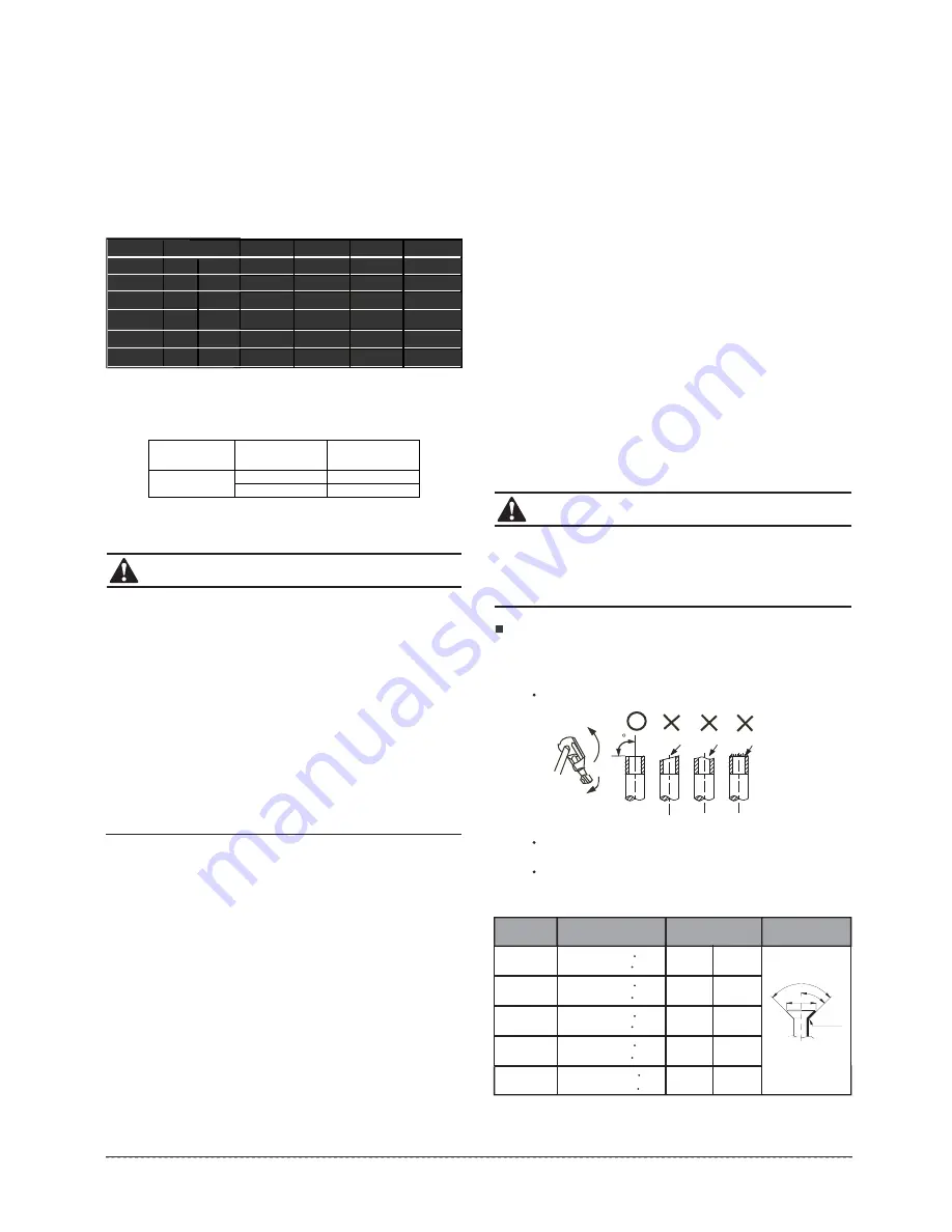
Flaring 

Cut a pipe with a pipe cutter. 

(refer to Fig.8-1) 

Ta b le  8-2 

Ø6.4 

8.3         8.3 

Ø9.5 

12.0       12.4 

Ø12.7 

15.4       15.8 

Ø15.9 

Ø19.1 

18.6       19.0 

22.9       23.3 

R0.4~0.8

45

°±

2

90

°     

±

4

A

Insert a flare nut into a pipe and flare the pipe. 
 
Refer to Table 8-2 for the dimension of flare nut spaces. 

Fig.8-1 

Pipe  gauge 


Tightening   torque 

Flare dimensin A 

Flare     shape 

90 

Lean     crude     burr 

11

installation manual 

min max 

(mm) 

14.2

17.2 N  m

(144

176 kgf  cm) 

32.7

39.9 N  m

(333

407 kgf   cm) 

49.5

60.3 N  m

(504

616 kgf  cm) 

61.8

75.4 N   m

(630

770 kgf   cm) 

97.2

118.6 N  m 

(990

1210 kgf  cm) 

Csapacit

Btu/h

12k

18k

24k

36k

48k

Ptipe size

GAS

LIQUID

 12'

 12'

(Ø12.7) 

 12'

(Ø12.7) 

 58''

(Ø16.0) 

 58''

(Ø16.0) 

 58''

(Ø16.0) 

 38''

(Ø9.52) 

 38''

(Ø9.52) 

 38''

(Ø9.52) 

 14''

(Ø6.35) 

(Ø6.35) 

 14''

Ptipe size

Standard

length

Max. 

Elevation

Standard

length

Max. 

Lenth

Additional

refrigerant

(ft)

(ft)

(ft)

(oz/ft)

25

25

25

25

25

98

98

82

66

33

213

164

98

82

213

213

0.320

0.160

0.160

0.320

0.320

Some systems require additional charging depending on pipe lengths. The standard pipe length 

varies according to local regulations. In North America, the standard pipe length is 7.5m (25ft). 

The additional refrigerant to be charged can be calculated using the following formula: 

Diameter  of  liquid  pipe 

(mm) 

Φ6.35mm 

1/4 in


Φ9.52 (3/8 in) 

Formula 

V=15g/m×(L-7.5) 

V=30g/m×(L-7.5) 

V=0.16oz/ft x (L-25ft) 

V=0.32oz/ft x (L-25ft) 

Содержание CPP012CD(O)

Страница 1: ...PA 12 TPA 18 TPA 24 TPA 36DU TPA 48DU Outdoor Unit CPP009CD O CPP012CD O CPP018CD O CPP024CD O CPP036CD O DU CPP048CD O DU If used as MULTI unit please refer to the Installation operation manuals pack...

Страница 2: ...strong and firm location which is able to withstand the set s weight If the strength is not enough or installation is not properly done the set will drop to cause injury The appliance must be installe...

Страница 3: ...not be sufficient enough to eliminate the noise The appliance is not intended for use by young children or infirm persons without supervision Don t install the air conditioner in the following locatio...

Страница 4: ...vement without further notices Cautions on remote controller installation Remote controller Remote controller holder Mounting screw B ST2 9x10 C H CANCEL LOCK SET TEMPERATURE C AUTO COOL DRY HEAT FAN...

Страница 5: ...INSPECTING AND HANDLING THE UNIT At delivery the package should be checked and any damage should be reported immediately to the service agent When handling the unit take into account the following 5...

Страница 6: ...y by wrenching the nuts after having adjusted the body s position well Refer to Fig 5 5 Select the position of installation hooks according to the hook holes on the installation board positions on the...

Страница 7: ...our corners if the lift of the indoor unit and the drainpipe is not influenced Refer to Fig 5 13 right Hang the air in grill to the panel then connect the lead terminator of the swing motor and that o...

Страница 8: ...ge test Check whether the drainpipe is unhindered New built house should have this test done before paving the ceiling The unit with pump Remove the test cover and stow about 2000ml water to the water...

Страница 9: ...g 5 19 Fig 5 18 One way Two way In case of one duct connection In case of two duct connection NOTE Fig 5 17 5 4 Install the distribution duct Conditioned air can be distributes by means of a distribut...

Страница 10: ...direct sunlight If necessary install a blind that does not interfere with the air flow During the heating mode the water drained off the outdoor unit The condensate should be well drained away by the...

Страница 11: ...lve of vacuum meter 2 Cut off the connection between pressure meter and vacuum pump 3 Close the vacuum pump Fig 6 7 NOTE All the pictures in this manual are for explanation purpose only They may be sl...

Страница 12: ...ell with the tapes to prevent leakage Execute heat insulation work completely on both sides of the gas piping and the liquid piping Otherwise this can sometimes result in water leakage 1 2 3 5 6 7 4 B...

Страница 13: ...orque N M Turn clockwise to close Stop Valve size Shaft valve body Cap Valve lid 6 4 5 4 6 6 Hexagonal 13 5 16 5 11 5 13 9 9 5 12 7 8 1 9 9 18 22 15 9 13 5 16 5 Hexagonal 23 27 22 2 27 33 Hexagonal wr...

Страница 14: ...ion 3 The drain plug is used to empty the water receiver for maintenance of the air conditioner Please stuff it imposition at all times during operation to avoid leakage The body s pump pipe and the d...

Страница 15: ...ment has to be connected with this power line For detailed installation acceptance please refer to your power supplier if restrictions do apply for products like washing machines air conditioners or e...

Страница 16: ...impeded The heating insulation works well The ground wiring is connected correctly The length of the tubing and the added stow capacity of the refrigerant have been recorded The power voltage fits the...

Страница 17: ...ding to the wiring scheme or it damages the unit Before obtaining access to terminals all supply circuits must be disconnected CAUTION Indoor Outdoor connection The power supply must comply with the r...

Страница 18: ...ls TECHNICAL BULLETIN Heat Sink Compound Thermal Paste Make sure to use Heat Sink Compound not provided when replacing Mini Split electronic boards Clean up thoroughly old paste on chips located under...

Отзывы: