background image

14

101810

CONNECTING

TO GAS

SUPPLY

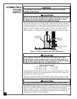
The installer must supply an external regulator. The external regulator will reduce
incoming gas pressure. You must reduce incoming gas pressure to between 11 and
14 inches of water. If you do not reduce incoming gas pressure, heater regulator
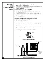
damage could occur. Install external regulator with the vent pointing down as
shown in Figure 13. Pointing the vent down protects it from freezing rain or sleet.

NOTICE

A qualified service person must connect heater to gas supply.
Follow all local codes.

Propane/LP
Supply Tank

Figure 13 - External Regulator With Vent Pointing Down

Typical Pipe Diameters

18,000 Btu/Hr Models

3/8" or greater

28,000 Btu/Hr Model

1/2" or greater

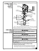
Installation must include a manual shutoff valve, union, and plugged 1/8" NPT tap.
Locate NPT tap within reach for test gauge hook up. NPT tap must be upstream
from heater (see Figure 14, page 15).

Apply pipe joint sealant lightly to male threads. This will prevent excess sealant
from going into pipe. Excess sealant in pipe could result in clogged heater valves.

Install sediment trap in supply line as shown in Figure 14, page 15. Locate sediment
trap where it is within reach for cleaning. Locate sediment trap where trapped
matter is not likely to freeze. A sediment trap traps moisture and contaminants. This
keeps them from going into heater controls. If sediment trap is not installed or is
installed wrong, heater may not run properly.

WARNING ICON

G 001

 CAUTION

Never connect heater directly to the propane/LP supply. This heater
requires an external regulator (not supplied). Install the external
regulator between the heater and propane/LP supply.

WARNING ICON

G 001

 CAUTION

Use only new, black iron or steel pipe. Internally-tinned copper
tubing may be used in certain areas. Check your local codes. Use
pipe of large enough diameter to allow proper gas volume to heater.
If pipe is too small, undue loss of pressure will occur.

WARNING ICON

G 001

 CAUTION

Use pipe joint sealant that is resistant to liquid petroleum (LP) gas.

External
Regulator

Vent Pointing
Down

Содержание CGP18TB

Страница 1: ...mediately call your gas supplier from a neighbor s phone Follow the gas supplier s instructions If you cannot reach your gas supplier call the fire department Installation and service must be performe...

Страница 2: ...injury or death from burns fire explosion electrical shock and carbon monoxide poisoning WARNING ICON G 001 DANGER Carbon monoxide poisoning may lead to death Carbon Monoxide Poisoning Early signs of...

Страница 3: ...xygendepletionsensor ODS pilotlightsafetysystem TheODSshutsdownthe heaterifnotenoughfreshairisavailable SeeAirforCombustionandVentilation pages 5 through 8 7 Keepallairopeningsinthefrontandbottomofhea...

Страница 4: ...shipment 3 Check heater for any shipping damage If heater is damaged promptly inform dealer where you bought heater PRODUCT FEATURES Safety Device This heater has a pilot with an Oxygen Depletion Sens...

Страница 5: ...1992 Section 5 3 defines confined space as having an air volume of less than 50 cubic feet 127 cubic cm for each 1000 Btu Hr input rating of all appliances in the space cubic feet equals length x widt...

Страница 6: ...heater ___________________ Btu Hr Gas fireplace logs ___________________ Btu Hr Other gas appliances ___________________ Btu Hr Total ___________________ Btu Hr Example Gas water heater 40 000 Btu Hr...

Страница 7: ...resh air would come from an adjoining unconfined space When ventilating to an adjoining unconfined space you must provide two permanent openings one within 12 of the ceiling and one within 12 of the f...

Страница 8: ...fresh air by using ventilation grills or ducts You must provide two permanent openings one within 12 of the ceiling and one within 12 of the floor Connect these items directly to the outdoors or space...

Страница 9: ...minimum clearances shown in Figure 4 page 10 If you can provide greater clearances from floor ceiling and join ing wall You can locate heater on floor away from a wall An optional floor mounting stand...

Страница 10: ...ttaching Thermostat Sensing Bulb 1 Remove thermostat sensing bulb from holders inside heater Route through slot opening in bottom of heater 2 Place clamp on thermostat sensing bulb as shown in Figure...

Страница 11: ...Attaching to wall stud 2 Attaching to wall anchor Attaching to wall stud This method provides the strongest hold Insert mounting screws through mounting bracket and into wall studs Attaching to wall a...

Страница 12: ...led in wall 3 Insert mounting screws through bracket and into wall studs 4 Tighten screws until mounting bracket is firmly fastened to wall studs Attaching to wall anchor method For attaching mounting...

Страница 13: ...Locate two bottom mounting holes These holes are near bottom on back panel of heater see Figure 12 2 Mark screw locations on wall 3 Remove heater from mounting bracket 4 If installing bottom mounting...

Страница 14: ...male threads This will prevent excess sealant from going into pipe Excess sealant in pipe could result in clogged heater valves Install sediment trap in supply line as shown in Figure 14 page 15 Loca...

Страница 15: ...eater regulator 2 Cap off open end of gas pipe where manual shutoff valve was connected An A G A design certified manual shutoff valve with 1 8 NPT tap is an acceptable alternative to test gauge conne...

Страница 16: ...orming show a leak 4 Correct all leaks at once PRESSURE TESTING HEATER GAS CONNECTIONS 1 Open manual shutoff valve see Figure 15 2 Open propane LP supply tank valve 3 Make sure control knob of heater...

Страница 17: ...gas control knob Never use tools If the knob will not push in or turn by hand don t try to repair it call a qualified service technician or gas supplier Force or attempted repair may result in a fire...

Страница 18: ...to the front of burner The pilot can be seen through the glass panel If needed keep pressing ignitor button until pilot lights Note If pilot does not stay lit refer to Troubleshooting pages 24 throug...

Страница 19: ...the room may exceed the set temperature If so the burner will shut off The burner will cycle back on when room temperature drops below the set temperature The control knob can be set to any heat leve...

Страница 20: ...pattern Figure 20 shows an incorrect pilot flame pattern The incorrect pilot flame is not touching the thermocouple This will cause the thermocouple to cool When the thermocouple cools the heater wil...

Страница 21: ...other fine particles enter the heater and burn causing brief patches of orange flame If burner flame pattern is incorrect as shown in Figure 22 turn heater off see To Turn Off Gas to Appliance page 19...

Страница 22: ...cessive lint from carpeting bedding material etc WARNING ICON G 001 WARNING Turn off and unplug heater and let cool before servicing Only a qualified service person should service and repair heater WA...

Страница 23: ...bly 7 Replace thermocouple 8 Replace control valve OBSERVED PROBLEM When ignitor button is pressed there is spark at ODS pilot but no ignition ODS pilot lights but flame goes out when control knob is...

Страница 24: ...d clean burner see Cleaning and Mainte nance page 22 2 Replace gas regulator 1 Problem will stop after a few hours of operation 1 Turn control knob to LO position and let warm up for a minute 2 Operat...

Страница 25: ...king noise just after burner is lit or shut off Heater produces unwanted odors Heater shuts off in use ODS operates Gas odor even when control knob is in OFF position Gas odor during combustion Moistu...

Страница 26: ...23 5 x 25 9 x 8 0 Carton 25 8 x 21 3 x 10 1 25 8 x 28 7 x 10 1 Weight pounds Heater 22 30 Shipping 27 35 SPECIFICATIONS SERVICE PUBLICATIONS You can purchase a service manual from the address listed...

Страница 27: ...o support our customer s needs by providing original replacement parts and accessories Baltimore Electric 1348 Dixwell Avenue Hamden CT 06514 1 800 397 7553 203 248 7553 Parts Department Portable Heat...

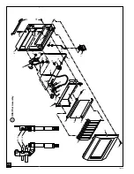
Страница 28: ...28 101810 1 2 3 4 5 6 7 8 9 10 10 11 12 13 14 15 16 17 19 20 21 22 23 24 25 26 27 28 30 31 32 18 12 ODS Pilot Assembly 31 30 29 12 1 12 2...

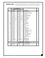
Страница 29: ...ervice Kit 1 12 1 098514 01 098514 01 Thermocouple 1 12 2 098515 01 098515 01 Ignitor Electrode 1 13 099120 02 099126 02 Burner 1 14 098517 01 098517 01 3 16 Pilot Tubing 1 15 098251 01 098251 03 Inje...

Страница 30: ...write to the address listed on the back page of this manual FLOOR MOUNTING STAND 18 000 Btu Hr Models GA4000B and GA4500 28 000 Btu Hr Model GA4010B and GA4510 For locating heater on the floor away fr...

Страница 31: ...31 101810 NOTES...
Страница 32: ...odes and instructions furnished with the unit This warranty does not apply to parts that are not in original condition because of normal wear and tear or parts that fail or become damaged as a result...

Отзывы: