IOM - SLEEVED PLUG VALVES, UNIFLOW PP
©COMEV
AL
V
AL
VE SYSTEMS
Technical Dept. Ref. IOM - SLEEVED PLUG V
AL
VES, UNIFLOW PP
- Ed.16/05
Comeval V
alve Systems reserves the right to alter any technical data contained in this Manual without prior notice. Regularly updated data on www
.comeval.es
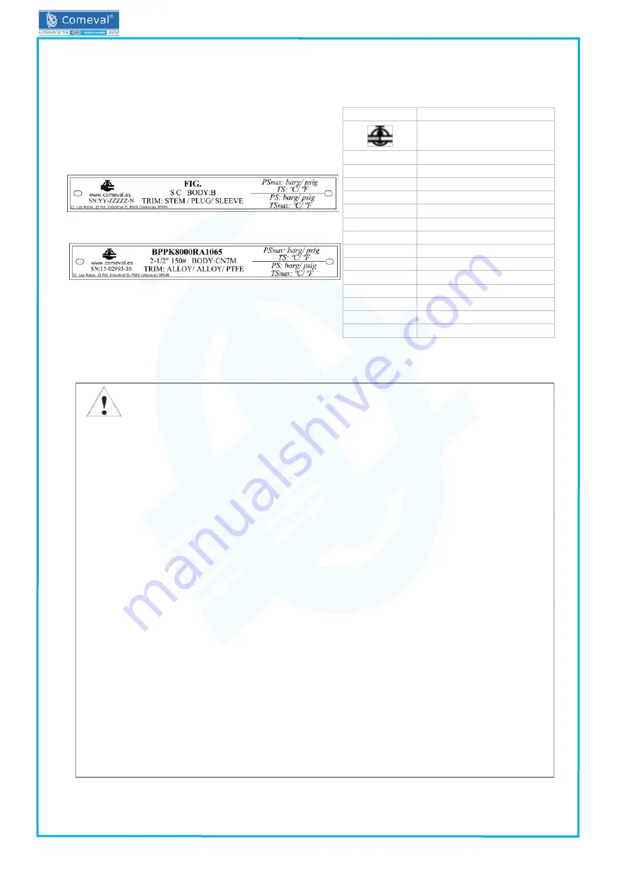
4.5 Marking/nameplate
Nameplate description of the valve:
5. – INSTALLATION
5.1 General remarks on installation
The following points should be taken into account in addition to the general principles governing installation work:
- Valves should be installed with in open position, making sure that the parts are perfectly aligned. Tighten bolts in an
uniform and crosswise manner.
ATTENTION!
- Remove flange covers or any other remaining packing/storage protection if present.
- The interior of the valve and the pipeline must be free of foreign particles.
- Valves are normally bidirectional. Some special designs are unidirectional, in such a case please follow the arrow
in the body for flow direction.
- Lay pipelines such that damaging transverse, bending and torsional forces are avoided.
- Protect valves from dirt during construction work.
- Protect the valve soft parts from heating caused by welding works at the plant during commissioning.
- Product parts such as levers, gears or actuators must not be used to take up external forces that they are not
designed for: e.g. do not use them as climbing aids, or as connecting points for lifting gear, etc.
- Suitable materials handling and lifting equipment should be used for assembly work. During assembly work,
ensure that the valve is fixed adequately. See data sheet for weights.
- Valve optimal position is horizontal with stem pointing upwards. Valves can alternatively be installed in vertical
pipelines. Try to avoid the stem pointing downwards.
- You must only operate the unmounted valve while observing all the safety measures.
- Avoid mechanical damage to the sleeve and plug during handling, storage and installation.
- Check correct position of nameplate and handle with care to avoid personnel cuttings.
-
When the valve is operated, there is a crushing hazard between the plug and the sleeve. Ensure the valve is not
under operation in case hands are introduced inside the valve.
- When using the valve as an end seal, the employers’ liability insurance association of the gas and waterworks
specifies the use of a safety precaution such as a plug-in disc, blind flange, etc. (observe the information in EN
13857). With a medium jet that freely exists, you must secure the exit area.
- Make sure that counter-flanges are compatible with the standard of the valve flanges. When matching up flanges,
avoid gradients, rotation and pipe misalignment that could cause pipe and valve stress and leakage once installed.
Flanges should fit smoothly. Select the proper flange face gaskets according to duty and centre them on the flange
face properly. Do not force the counter-flanges and do not try to tighten the bolts when a gap exists between valve
and pipe or if misalignment is observed. Tighten in a crosswise, moderate and uniform manner. During start-up
tighten again if leakage is noticed or replace gasket if necessary.
Actuator:
If the valve requires pneumatic, electric or hydraulic actuators, separate actuator Manual shall be also
followed. To avoid unnecessary stress and risk of valve break, consider the weight and the relative position of
actuator to evaluate its support. Make sure that the actuator is suitable for service particular requirements, valve
adaptability, function needed, adequate torque for the valve, need for limit switches, etc. Contact our Technical
Department for advice. In case of actuator mounted, you must disconnect the energy supply before starting work.
Page 3
Mark
Description
Manufacturer logo
www.comeval.es
Website of manufacturer
FIG.
Valve code
YY
Manufacturing year
SN: ZZZZZZZ-N
Batch / Serial no.
S
Valve size
C
Valve class
B
Body material
STEM
Stem material
PLUG
Plug material
SLEEVE
Sleeve material
PSmax
Max. pressure
TS
Max. temperature at max. pressure
PS
Max. pressure at max. temperature
TSmax
Max. temperature
Example


