


www.comdronic.co.uk
Display Menu
There are four different display formats available for the
AC7
. The most appropriate format will depend on the
type of valve / device being measured and the commissioning method being applied. The four display formats
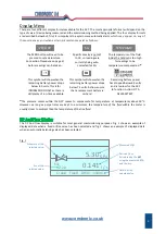
are described below but, first, it is important to explain some automatic alerts
which may appear on any of
these screens as and when certain circumstances exist as follows:
*
The pressure sensor within the
AC7
ceases to compensate for temperature at temperatures above 50°C.
However, as long as purge times are kept to a minimum, the temperature of the fluid within the meter is
usually closer to ambient than the temperature of the line fluid.
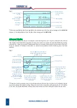
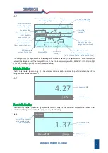
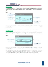
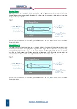
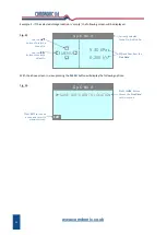
The DP And Flow Display is suitable for most general commissioning purposes. Fig. 1 shows an example of
displayed data when a fixed orifice valve has been selected and fig. 2 shows an example of displayed data
when an automatic balancing valve has been selected.
Fig. 1
5
Schematic of the
selected valve.
Kvs of the
selected valve.
Details of the
selected valve.
Derived Flow.
Calculated by the
AC7
using the measured
Δp
and the Kvs.
Measured
Δp
.
5.30
Crane Fixed D931 15mm
KPa
l / s
0.141
Kvs
2.20
ZERO DP
SG
TEMP HIGH
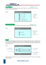
This symbol will show when the
remaining battery power drops
below 8.0 volts. This is for
INFORMATION ONLY as there is
still plenty of run-time available.
The
ZERO
button will need to be
pressed to set a datum (see
Connection Procedure on page 3)
before readings can be taken.
Specific Gravity is not set
to 1.0, so readings are
currently being auto-
corrected for SG.
The temperature of the fluid
inside the handset is too high
for readings to be
temperature-compensated.
*
Remaining battery power
has dropped below 6.5 volts
and is too low for the
AC7
to function. Action: FIT A
NEW BATTERY.
This symbol will show when the
remaining battery power drops
below 7.5 volts. Action: ensure
that a replacement battery is
on-hand.
Содержание AC7
Страница 2: ...www comdronic co uk ...
Страница 22: ...www comdronic co uk User Notes ...