


EQUIPMENT MANUAL FOR SP-2110
SP-2110 QE
Copyright - refer to title page
Page 29
ENU Status : 1-3-1
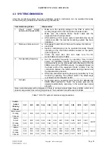
Table 8: Comparison between swich-setted working channel and actual working channel
0
8
4
C
1 2
3
5
6
7
9
A
B
D
E F
CH1
CH2
CH3
CH5
CH4
CH7
CH8
CH9
CH10
CH11
CH12
CH6
Freq
Control
Software
Set
0
8
4
C
1 2
3
5
6
7
9A
B
D
E F
0
100
200
400
300
600
700
-700
-600
-500
500
-400
-300
-200
-100
kHz
Freq
Offset
0
8
4
C
1 2
3
5
6
7
9
A
B
D
E F
60
58
56
52
54
48
46
42
40
38
50
36
34
32
Auto
44
Gain
0
8
4
C
1 2
3
5
6
7
9
A
B
D
E F
CH1
CH2
CH3
CH5
CH4
CH7
CH8
CH9
CH10
CH11
CH12
CH6
Freq
Control
Software
Set
0
8
4
C
1 2
3
5
6
7
9A
B
D
E F
0
100
200
400
300
600
700
-700
-600
-500
500
-400
-300
-200
-100
kHz
Freq
Offset
0
8
4
C
1 2
3
5
6
7
9
A
B
D
E F
60
58
56
52
54
48
46
42
40
38
50
36
34
32
Auto
44
Gain
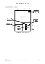
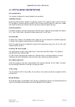
Fig 12: Function of dial switches
Note: On the “Freq Control” dial-switch, the “Software Set” and “D”, “E”, “F” are reserved function for
future usage, and are not to be used.
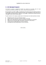
4.4 MCU RESET
If it is required to reset the system when a lockup occurs, press and momentarily hold the “Reset
Switch” located on the MCU. After releasing, all LED should be extinguished momentarily to indicate
the system is being initialized. Initialization will take approximately two seconds.
End of section


