


EQUIPMENT MANUAL FOR SP-2110
SP-2110 QE
Copyright - refer to title page
Page 27
ENU Status : 1-3-1
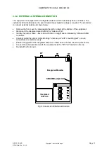
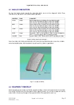
4.1 MCU LED INDICATORS
On the front panel, locate beneath the removable LEDs cover are five diagnostic LEDs. There
indications are described in the following table separately:
Identifier Color
Indication
HIGH
Green
RSSI indicator which indicates the input field strength.
ON= the DL input field strength is more than -40dBm.
OFF= the DL input field strength is less than -40dBm
MID
Green
RSSI indicator which indicates the input field strength.
ON= the DL input field strength is more than -50dBm.
OFF= the DL input field strength is less than -50dBm
LOW
Green
RSSI indicator which indicates the input field strength.
ON= the DL input field strength is more than -60dBm.
OFF= the DL input field strength is less than -60dBm
RUN
Green
Operation. ON= normal operation, flash= during initialization
OFF = no power supply / MCU operating problem
ALARM
Red
System Alarm, ON = Failure Alarm, OFF= operating normally
Table 6: LEDs colour and indication
Note: the LEDs LOW, MID and HIGH will be OFF when the input fileld strength is more than -30dBm,
while the ALARM will be ON to indicate an Input Power Over Alarm is generated.
Fig 11: Location of LEDs
4.2 EQUIPMENT POWER-UP
Before applying power, make sure that the expected voltage, current, and power levels do not violate
any ratings. Double check all connections before applying power. Do not touch equipment internal
power units or make any changes to the equipment when the equipment is power up.


