background image

USER MANUAL FOR COMFLEX-6900 


ENU STATUS : 1-0-0 

Copyright - refer to title page 

Page 57 


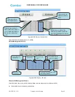
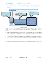
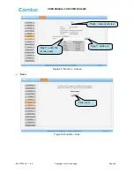
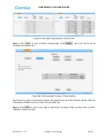
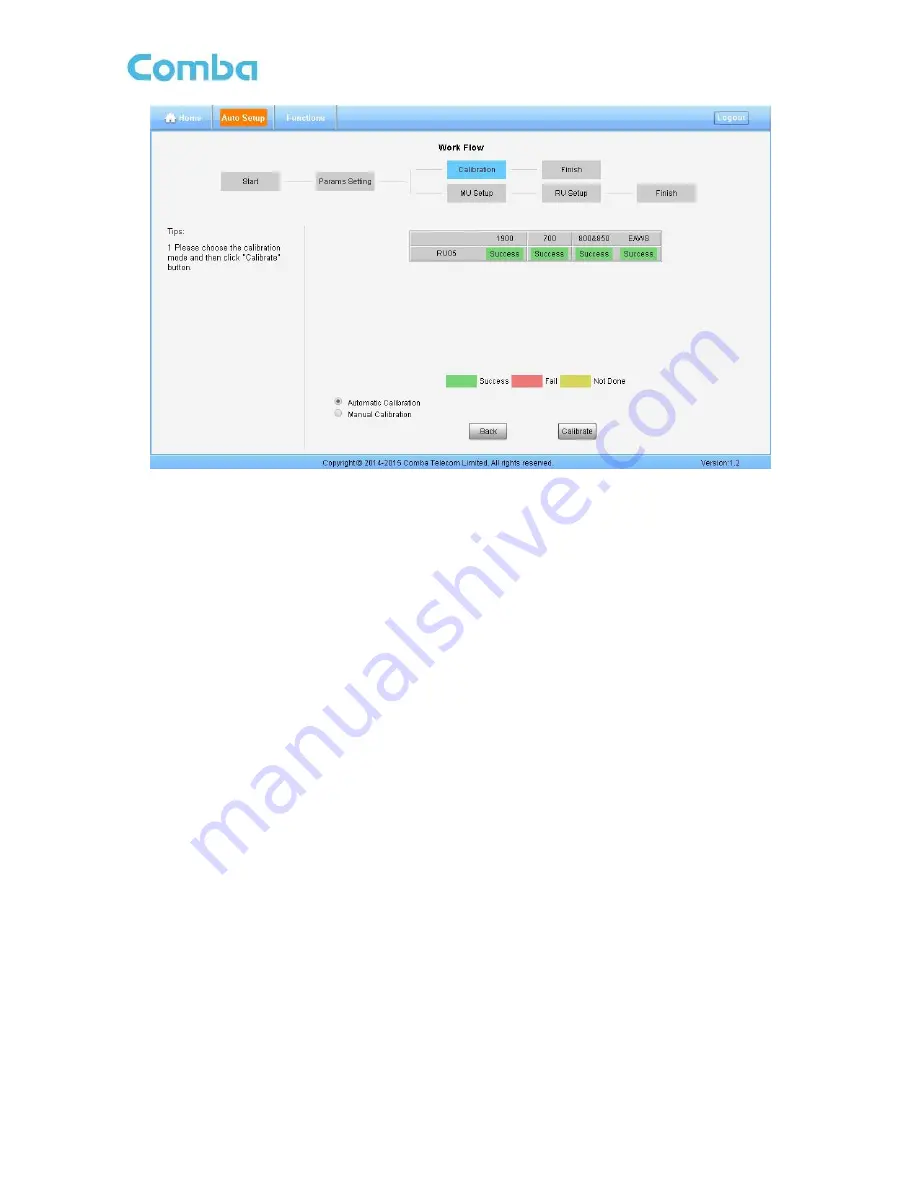
Figure 68: Flow to select 


Automatic  calibration  no  needs  to  select  frequency  band,  the  system  will  calibration  all  the 

band automatically. 


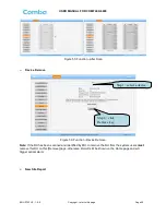
If  users  choose  Manual  calibration,  then  go  to  next  page  to  select  frequency  band  to 

calibrate. 


Note: 

Make  sure  the  ANT  port  of  RU  is  connected  with  dummy  load  or  antennas  before  Calibration.    

Several RU can be calibrated simultaneously. 


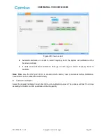
Automatic calibration 


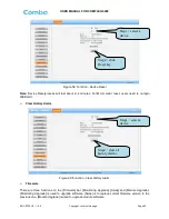
Select “Automatic Calibration”, and click OK to goto calibration process. The process will last 1-5 minites 
according to the MU and RU quantities and band quantity. 


Содержание ComFlex-6900

Страница 1: ...D DI IS ST TR RI IB BU UT TE ED D A AN NT TE EN NN NA A S SY YS ST TE EM M USER MANUAL ComFlex 6900 QE 1 0 0 Comba Telecom Ltd ComFlex 6900...

Страница 2: ...Comba International Comba All rights reserved The information contained herein is confidential and the property of Comba and is supplied without liability for errors or omissions No part may be repro...

Страница 3: ...TALLATION 16 3 1 WARNINGS AND ALERTS 16 3 2 SITE PLANNING CONSIDERATIONS 17 3 2 1 SITE PLANNING 17 3 2 2 SYSTEM INSTALLATION CHECKLIST 18 3 3 INSTALLATION PROCEDURES 18 3 3 1 GOODS INWARDS INSPECTION...

Страница 4: ...PLAY INDICATORS 38 4 3 1 DIGITAL DISPLAY ON RFU 38 4 3 2 DIGITAL DISPLAY ON FOU 38 5 WEB GUI 40 5 1 WEB GUI CONNECTION 40 5 2 WEB GUI INTRODUCTION 41 5 2 1 HOME 41 5 2 2 AUTO SETUP 45 5 2 3 FUNCTION 4...

Страница 5: ...MU Rear Panel Connectors 29 Figure 24 MU Warning Lable 30 Figure 25 MU Grounding MU Rear Panel 30 Figure 26 RU Grounding 31 Figure 27 Fiber Optical and RF Port Connection 32 Figure 28 MU Power Connect...

Страница 6: ...ommissioning Procedure Params Setting 55 Figure 67 Flow to select 56 Figure 68 Flow to select 57 Figure 69 Commissioning Procedure Automatic Calibration 58 Figure 70 Commissioning Procedure Calibratio...

Страница 7: ...USER MANUAL FOR COMFLEX 6900 ENU STATUS 1 0 0 Copyright refer to title page Page 7 0 3 HISTORY Change No ENU Details Of Change 1 1 0 0 This user manual first created in February 2018...

Страница 8: ...obile Terminal MTBF Mean Time Between Failures MU Master Unit NC Normally Closed NF Noise Figure NO Normally Open OMC Operation Maintenance Center OMT Operation Maintenance Terminal OP Optical Fiber O...

Страница 9: ...thority to operate the product NOTE Note The grantee is not responsible for any changes or modifications not expressly approved by the party responsible for compliance Such modifications could void th...

Страница 10: ...nd 2500MIMO band The low signal transmission loss of optical fiber is applicable for long distance transmission ComFlex can support the optical transmission of up to 6 5dBo optical loss equivalent to...

Страница 11: ...USER MANUAL FOR COMFLEX 6900 ENU STATUS 1 0 0 Copyright refer to title page Page 11 Figure 2 Remote Unit RU End of Section...

Страница 12: ...the signals are transmitted from RU ANT port to the service antenna using 50Ohm coaxial cable On the UL the signals transmitted by the mobile are converted into optical signals and then via the UL op...

Страница 13: ...oltage into stable DC to supply power for other modules of Master Unit MU01 FOU Master Unit Fiber Optical Unit FOU completes optical signal and RF signal conversion One FOU has four optical ports whic...

Страница 14: ...T Table 3 Master Unit MU KOP Item Qty Image MU Chassis 1 RF Unit RFU 1 8 Fiber Optical Unit FOU 1 2 Optical Extention Unit 1 Power Supply Unit PSU 1 Power Supply Cable 13 Feet 1 inch 1 Communication C...

Страница 15: ...s 8 Plain Washers 8 used for securing Remote Unit when hanged on bracket protrusions 2 pieces each Masonry Bolt set M10x110 used for wall mount installations 6 Hose Clamp 30 125 used for pole mount in...

Страница 16: ...involving installation operation or maintenance must be free from danger as far as reasonably possible Where there is a risk of damage to electrical systems involving adverse weather extreme temperat...

Страница 17: ...such as large electrical equipment Environmental Humidity has an adverse effect on the reliability of the equipment It is recommended to install the equipment in locations having stable temperature a...

Страница 18: ...the equipment will be operated within the stated environment refer to datasheet Where needed couple BTS RF signal with a coupler to prevent damaging the equipment Where appropriate confirm available...

Страница 19: ...is 3cm 1 2 3 3 4MU ASSEMBLING ComFlex Master Unit consists of 4 parts Chassis RFU FOU and PSU All the units are packed separately Follow the steps below to assemble Figure 5 ComFlex Master Unit Step1...

Страница 20: ...ight side of Chassis insert PSU and fasten the screws Figure 8 PSU Installation 3 3 5MU IN 19 RACK MOUNTING MU is an indoor type device the installation procedures are shown as below Step 1 Install ri...

Страница 21: ...USER MANUAL FOR COMFLEX 6900 ENU STATUS 1 0 0 Copyright refer to title page Page 21 Figure 9 Mounting Rack Figure 10 Angle Iron Installation...

Страница 22: ...S 1 0 0 Copyright refer to title page Page 22 Step2 Slide the MU on to the angle brackets and confirm it is level Figure 11 MU Installation Step 3 Attach the MU onto the rack with the recommended rack...

Страница 23: ...s Ventilated and easy to reach area for maintenance and on site inspection Proximity to DAS antenna in order to minimize cable loss Step 2 Using the mounting bracket top and bottom mounting holes as a...

Страница 24: ...ng Brackets to the wall with the protruding M8 nuts facing towards you The remote unit will be hung on these Figure 14 Install Mounting Rack on the Wall Step 4 Connectors facing down carefully fit and...

Страница 25: ...mounting bracket as shown below Figure 16 Tighten the Screws at the Bottom of RU Step 6 Check enclosure position and verify that unit is mounted securely to the wall 3 3 7Pole Mount Installation Step...

Страница 26: ...0 Copyright refer to title page Page 26 Step 2 Secure the mounting bracket by slipping the 5 hose clamps provided through the mounting bracket and tighten securely Figure 17 Mounting Rack of Pole Inst...

Страница 27: ...Connectors facing downwards hook the GX Quad on to the top part of the bracket and then to the bottom Figure 19 Hang on RU Step 4 Using a spanner or wrench tighten the two 2 M8 nuts on the top and bot...

Страница 28: ...6900 ENU STATUS 1 0 0 Copyright refer to title page Page 28 Figure 21 Finish Installation 3 4 EQUIPMENT CONNECTORS The figures below present the connectors of ComFlex MU 1 2 3 4 5 6 7 8 Figure 22 MU...

Страница 29: ...equipment for local and remote monitoring 5 LAN Reserved RJ45 port for remote monitoring 6 TX RX RF access port Mini Din connector 7 RX RF access port Mini Din connector 8 Digital display tube See cha...

Страница 30: ...ight side of RU with two M6 10 hexagon Screws screws are provided Connect the other side of the supplied copper wire GND cable to the building EARTH with two M6 screws screws are not provided Step 2 C...

Страница 31: ...f the RU OP port NOTE requires Single Mode fiber with SC APC connectors MAXIMUM OPTICAL LOSS 6 5dBo Step 2 For duplex application connect the MU RFU TX RX port to the RF Source BTS or BDA For simplex...

Страница 32: ...l commissioning Remote monitoring port BTS Alarm Reserved Fiber optic port RF port to BTS LED indicator Figure 27 Fiber Optical and RF Port Connection Step 3 Connect the power cable to the power suppl...

Страница 33: ...the OptiTap optical fiber to RU OP optic port and one of the OP port located on MU FOU front panel Figure 29 MU Power Connection Rear Panel Step 2 Rotation outer shell to tighten the fiber conncetion...

Страница 34: ...U STATUS 1 0 0 Copyright refer to title page Page 34 Step 4 Connect power cable on PSU with the public power grid 110 220VAC 14Amp maximum Figure 31 Power Supply Connection Figure 32 RU Fiber Optical...

Страница 35: ...alarms can be signaled to the BTS via voltage free relay contacts The voltage free relay connections are connected to the DB 9 port BTS_ALAM located on the MU The following figure and table show the p...

Страница 36: ...e 36 3 5 8CONNECT TO PC The local commissioning and management for MU and RU is achieved through connecting to the WEB base GUI Connect MU to PC Connect MU OMT port RJ45 to the RJ45 port of PC with su...

Страница 37: ...xt section 4 2 LED INDICATORS Diagnostic LEDs are located on the MU front panel and RU bottorm panel each indicates the status of a particular function Table 7 MU LED Indications LED Indicator Normal...

Страница 38: ...r is higher than 33 it will display H Figure 35 RFU Digital Display Table 9 RFU Digital Display Figure DL Input Power Level L 19dBm 19 33 19 33dBm H 33dBm 4 3 2DIGITAL DISPLAY ON FOU The digital displ...

Страница 39: ...USER MANUAL FOR COMFLEX 6900 ENU STATUS 1 0 0 Copyright refer to title page Page 39 Table 10 FOU Digital Display Figure Optical Loss 0 9 0 9dBo H 9dBo End of Section...

Страница 40: ...rnet cable to set up a physical connection Step 2 Go to laptop Control Panel Network and Internet Local Area Connection Right click it and click Properties Then follow the steps shown in figure below...

Страница 41: ...e 39 Input User Name and Password 5 2 WEB GUI INTRODUCTION After login the Web GUI main screen will appear Figure 40 Web GUI Main Screen On Comba Web GUI Home page there are four Menu bars Home Auto S...

Страница 42: ...reen Figure42 MU Device Monitoring Unit Optical Unit Management Screen Click here for RU main management page Click here for MU main management page Click here for FOU main management page Click here...

Страница 43: ...two steps are done before visit RU RU and MU are connected by optical fiber Slot number RF parameter Commissioning status Downlink input power overdrive alarm Click here to ON OFF RF switch and modify...

Страница 44: ...detect the PA output power and reflected power if they are normal the PA Service Status will turn to Normal if PA output power or reflected power is still over the threshold PA Service Status will tu...

Страница 45: ...commissioning process is shown on Auto Setup page Click the Start button the software will guide you through the commissioning step by step For details please refer to chapter 5 3 Figure 47 Auto Setup...

Страница 46: ...ngement page Below figures are the introduction of each function bar Devic Info Figure 48 Function Device Info Note Users can input maximum 30 bytes characters in Device Info Import Export Figure 49 F...

Страница 47: ...RF Switch RF Switch SNMP parameter Over temperature alarm threshold DL over output power threshold External Alarm level Import and Export can help users quickly configure MU and RU parameters For exa...

Страница 48: ...2 Function IP Setting Note For remote monitoring the IP Address must be set correctly according to the location IP of remote connection If there is more than one equipment is connected to the public n...

Страница 49: ...AL FOR COMFLEX 6900 ENU STATUS 1 0 0 Copyright refer to title page Page 49 Figure 53 Function License Scan Figure 54 Function Scan Step1 select a device Step2 enter the license code Step3 click set Cl...

Страница 50: ...ice Remove Figure 56 Function Device Remove Note If the RU has been scanned and identified by MU to remove the RU from the system users must remove this RU on this Remove page otherwise RU will still...

Страница 51: ...A Reset Figure 58 Function PA Reset Note PA will be turned off by software when PA output power or VSWR reflected power is exceed the threshold Users need to reset PA after debugging Device Reset Step...

Страница 52: ...UI Clear History Alarm Figure 60 Function Clear History Alarm Firmware There are three functions on the Firmware bar Monitoring Upgrade Swap and Module Upgrade Monitoring Upgrade is used to upgrade so...

Страница 53: ...e page Page 53 Figure 61 Function Firmware Alarm Log Figure 62 Function Alarm Log WebOMT Setting Step1 select a device Step2 click to select software that to be updated Step3 click to upgrade software...

Страница 54: ...OMT Setting 5 3 COMMISSIONING PROCEDURE To complete the installation and commissioning users need to follow the steps below Step 1 Click Menu bar Auto Setup on home page a work flow will show up Figur...

Страница 55: ...ers can set the device information and system time Figure 66 Commissioning Procedure Params Setting Dev Info mainly used to record device location and Date Time provid a time reference Mouse clicks th...

Страница 56: ...r been calibrated users click in the step of Calibration software can still procede to the next step of MU and RU setup but the system gain will be a little deviation with normal valuer so the final o...

Страница 57: ...ly If users choose Manual calibration then go to next page to select frequency band to calibrate Note Make sure the ANT port of RU is connected with dummy load or antennas before Calibration Several R...

Страница 58: ...atic Calibration After calibration the status of calibration will change Success from Not Done the colour change from yellow to green at the same time Finishing calibration then user can go to setup f...

Страница 59: ...rocedure MU Setup Step 7 Click to enter to RU Setup page after finishing MU setup Figure 72 Commissioning Procedure RU Setup Two parameters need to be set in this step RF Switch Set the RF switch stat...

Страница 60: ...nd they have the same input power level each channel will reach it s rated power so the total output power will be input A gain inputB gain inputN gain For example if there are two 1900MHz bands acess...

Страница 61: ...0 by default Optical Tx Alarm Alarm when Optical Transmiting power is lower than the threshold otherwise normal Alarm judgment period 3 minutes by default Alarm threshold 7dBm by default Optical Rx Al...

Страница 62: ...he threshold otherwise normal Alarm judgment period 3 minutes by default Alarm threshold 48dBm Shutdown Alarm Alarm when the PA status is off otherwise normal Alarm judgment period 10s by default LNA...

Страница 63: ...MU transmit optical power is normal 4 2dBm Check if optical loss of fiber link is higher than 6 5dBo Clean fiber connector with absolute ethanol DL PA alarms Check PA Service Status on WEB GUI RU pag...

Страница 64: ...PPENDIX A TOOLS FOR INSTALLATION AND MAINTENANCE The following tools not included in package are required for installation or routine maintenance Power Drill for wall mount Adjustable Wrench 0 31 inch...

Страница 65: ...R COMFLEX 6900 ENU STATUS 1 0 0 Copyright refer to title page Page 65 7 2 APPENDIX B RMA RETURN MATERIAL AUTHORIZATION End of Section End of Document FOR NAM OFFICE EMAIL PLEASE INSERT support us comb...

Страница 66: ...USER MANUAL FOR COMFLEX 6900 ENU STATUS 1 0 0 Copyright refer to title page Page 66...

Отзывы: