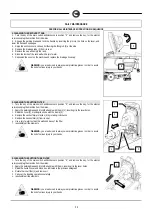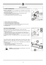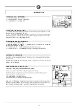
14
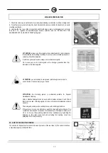
MACHINE PREPARATION
8.
Detergent solution flow quantity knob
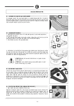
12. REAR COMPONENTS
The rear components are identified as follows:
9.
Brush lifting pedal
10.
Water level tube
11.
Solution filter
12.
Discharge pipe with recovery tank cap
13.
Tank closure hinges
14.
Handlebar fastening screws
15.
Squeegee lifting lever
16.
Brake lever
17.
Solution tank drainage cap
18.
Key switch and circuit breakers
13. SIDE COMPONENTS
The side components are identified as follows:
19.
Solution water filler cap
20.
Recovery tank lifting handle
21.
Suction unit lifting handle
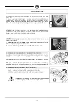
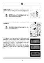
14. SQUEEGEE ASSEMBLY
For packaging reasons, the squeegee is supplied disassembled from the machine, and must be
assembled on the machine connection. The squeegee connection must be lifted by means of the lever
at the rear of the machine and the following procedure carried out:
1.
Verify that the main switch of the machine is in the "0" position, if not do so, for the electric versions
make sure the power supply is disconnected
2.
Raise the squeegee and insert the small left-hand column (1) in the connection hole
11
12
13
14
15
16
18
17
9
10
20
19
18
8


