9
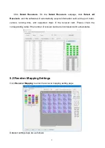
5.2.1 Mapping Settings
Select the target Ethernet port on the left side, and then select
the corresponding
cabinets within the actual control area of the port and set the connection lines in the
simulated cabinet area.
In the simulated cabinet area, select the corresponding cabinet of the first receiver card
based on the actual connection of the Ethernet port (view from the front), and left-click the
cabinet one by one according to actual connecting line, until the last one this Ethernet port
controls.
For the cabinets with different specifications (different in dimensions), you can select
them and adjust the mapping separately after setting.
5.2.2 Saving Mapping
After successively setting the cabinets each port controls and their mapping, click
Send
and
Save to Devices
at the bottom of the window to send and save the mapping to
the current sender and receiver cards.
Содержание X20
Страница 1: ...X20 Controller ...
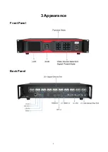
Страница 5: ...3 3 Appearance Front Panel Back Panel ...
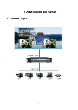
Страница 7: ...5 4 Application Scenarios 4 1 Ethernet Output ...
Страница 8: ...6 4 2 Optical Fiber Output ...
Страница 32: ...30 ...


