


www.colmac.ie
25
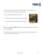
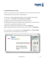
The E18 chip has the following features:
8 digital outputs labelled Q0 to Q7
We are only using Q3 to Q7 incl. for this line follower robot
These outputs are ‘digital’ in that they are either on (1) or off (0)
3 possible analogue inputs e.g. LDR, Thermistor etc. labelled A0, A1 and A2
5 possible digital inputs e.g. switches labelled D0, D1, D2, D6 and D7
As shown on the chip configuration:
o
Input A0 and D0 share Pin 17 – connected to A/D0 on PCB
o
Input A1 and D1 share Pin 18 – connected to A/D1 on PCB
o
Input A2 and D2 share Pin 1 – connected to A/D2 on PCB
We are only using A/D0 and A/D2 for this line follower robot
Power to the chip can be tested across Pin 5 (0v) and Pin 14 ( should be at least 3.5 to 9v)
Number of inputs and outputs available
Chip configuration
NOTE:
We are only using LDR inputs in this
robot but it is possible to use many
other analogue inputs such as a
thermistor, variable resistors etc. with
the GENIE E18.
Similarly it is possible to incorporate
digital inputs such as micro switches
with the robot for obstacle avoidance.
etc. but they are not covered in this