Get it all with just one call
1-800-444-1198
All registered and unregistered trademarks are the property of their respective
owners. Specifications subject to change without notice. Patent 7,375,737 and
others pending.
Copyright © 2017 by Codonics, Inc. Printed in the U.S.A. Part No. 901-222-003.02
17991 Englewood Drive
Middleburg Heights, OH
44130 USA
+1.440.243.1198
+1.440.243.1334 Fax
Email [email protected]
www.codonics.com
Codonics Limited KK
AQUACITY 9F,
4-16-23, Shibaura
Minato-ku, Tokyo,
108-0023 JAPAN
81-3-5730-2297
81-3-5730-2295 Fax
Codonics Trading Co, Ltd.
317 Xianxia Rd. Building B
Unit 1412
Changning Dist., Shanghai
P.R. China, 200051
86-21-62787701
86-21-62787719 Fax
10. Run the following commands to calibrate the Pick
Heights:
◆
Calibrate the Printer Height:
Place a disc in the print
tray and type
BravoComm.exe -n 171
at the
command prompt.
◆
Calibrate the Top Drive Height:
Open the top drive,
place a disc in the drive tray and type
BravoComm.exe -n 172
at the command prompt.
◆
Calibrate the Bottom Drive Height:
Open the bottom
drive, place a disc in the drive tray and type
BravoComm.exe -n 173
at the command prompt.
11. Delete
C:\opt\codburn.pause.yes
12. Bring back the Virtua GUI with W Shift + M
oìååáåÖ=íÜÉ=oçÄçíáÅ=^êã=`óÅäÉ=qÉëí
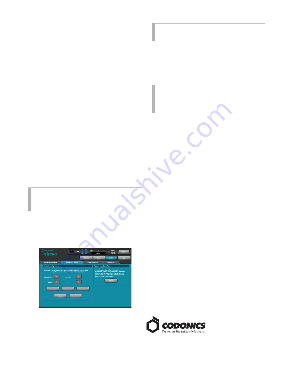
The Robotic Arm Cycle Test moves optical discs between all
of the Virtua components so that the correctness of
calibration can be viewed. Place no more than 50 optical
discs into one bin (the maximum for one bin) in the Virtua
system so that the progress of the testing can be easily
monitored. To prevent potential confusion after the test, use
a single variety of optical discs. The use of new optical discs
is not necessary.
Ideally, allow the Recorder to move 50 optical discs from the
right bin to the left bin and then back to the right bin without
mishandling errors to verify that calibration is correct. This
self test will take approximately 50 minutes to complete.
1. To begin the test, press the
Start
button in the
Robotic
Arm Cycle Test
section. A
Robot Test Running
message
and flashing green light will display on the dashboard. A
yellow light will be indicated if one input bin is empty.
The test will continue until the user presses the
Cancel
button to stop the test.
2. If additional calibration is required, follow the above
calibration process until satisfied. Re-run the Robotic
Arm Cycle Test (step 1).
3. If the optical drives have been moved (reference the
Optical Drive section, Steps 6 through 12), proceed to
Step 4. Otherwise, Virtua will be functional at this point.
4. Remove the optical discs and input bins.
5. Power down the Virtua system.
6. Disconnect the USB cable and eSATA cables from the
Recorder and switch off the power supply switch on the
rear of the Recorder.
7. Use the Torx driver to torque the screws securing the back
of the drive bay to approximately 6 in-lbs (0.68 Nm).
8. Install the Recorder on the Controller by reconnecting the
USB cable and eSATA cables to the Recorder and switch
on the power supply switch on the rear of the Recorder.
9. Power up the Virtua system.
10. Complete a final verification by burning a couple of
study discs.
=
qÉÅÜåáÅ~ä=pìééçêí
If problems occur during calibration, contact Codonics
Technical Support between the hours of 8:30AM and
5:30PM EST (weekends and U.S. holidays excluded).
Phone:
+1.440.243.1198
Email:
Website:
www.codonics.com
NOTE:
The Recorder cover should be closed for this test.
Problems during the test may require opening the cover
to correct the situation and any optical discs within the
drives will be cleared before resuming the test.
NOTE:
When resuming normal operation, the software
re-initializes the Recorder and clears any remaining
optical discs from the drives and printer tray.
NOTE:
Since waiting jobs may have accumulated within
Virtua during the calibration process, assure that the
correct variety of optical discs is placed into the
appropriate input bin afterwards to prevent subsequent
delays due to incorrect media selection.


