páÇÉJíçJëáÇÉ=Å~äáÄê~íáçå=Ñçê=~ää=oÉÅçêÇÉêë
15. If the optical disc position is too far left or right, adjust
the
Bottom Drive Tray
calibration value to move the
robotic arm left and right. Reselect the
Pick
or
Move
button to verify the new location.
16. Press the
right arrow
button or
left arrow
button until
Top
Drive Tray
appears as the
Component.
17. Press the
Drop
button to have the robotic arm place the
optical disc in the top optical drive tray.
18. Verify that the robotic arm is placing the optical disc as
shown in step 4. If calibration is needed, perform steps 6
through 14.
fåéìí=_áå
The following steps define how to calibrate the picking
position from the input bins.
1. Press the
right arrow
button or
left arrow
button until
Left
Bin
appears as the
Component
.
2. Press the
Move
button to have the robotic arm hold the
optical disc at the top of the bin.
3. If the optical disc position is too far left or right, adjust
the value to move the robotic arm right and left. Reselect
the
Move
button to verify the new location.
4. Press the
Drop
button to drop the optical disc into the left
bin.
5. Press the
Pick
button and carefully watch the optical disc
position relative to the bottom of the bin. If the optical
disc is not centered, average the optimal top and bottom
position for the final bin calibration setting.
6. Repeat steps 1 through 5 on the right bin.
mêáåíÉê=qê~ó
The following steps define how to calibrate the picking
position from the printer tray.
1. Press the
right arrow
button or
left arrow
button until
Printer Tray
appears as the
Component
.
2. Press the
Drop
button to have the robotic arm place the
optical disc in the printer tray.
3. If the optical disc position is too far left or right, adjust
the calibration value to move the robotic arm right and
left. Reselect the
Pick
or
Move
button to verify the new
location.
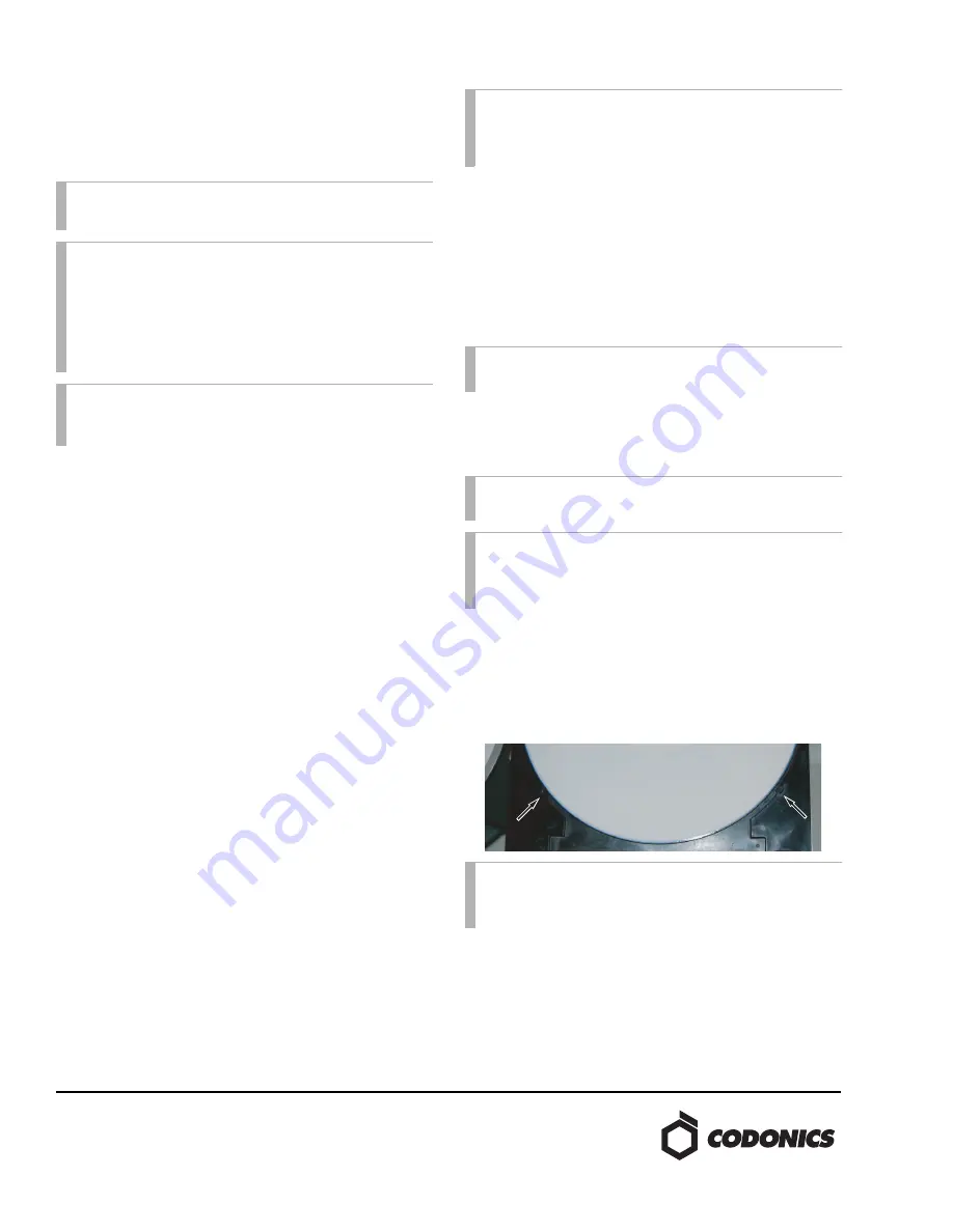
4. If the optical disc position is too far forward in the printer
tray and coming close to the two disc stops (shown
below), this could indicate that the printer tray is being
pulled back by the disc tab retention spring. If the printer
tray is pulling back, the optical discs could become
dislodged when the printer tray is retracted. Please contact
Codonics Technical Support for further instruction.
NOTE:
If unable to achieve center, bias the optical disc
towards the right of center.
NOTE:
As a final check, it is recommended to move the
robotic arm to another location and return back to the
bottom optical drive. Complete a final check of optical
disc location by selecting the
Drop
button on the
Bottom
Drive Tray
component. Having the robotic arm move
from and back to the calibration location ensures the
robotic arm has accurately read the encoder position.
NOTE:
Press
Pick
button to remove the optical disc from
the bottom optical drive before proceeding to the next
step.
NOTE:
As a final check, it is recommended to move the
robotic arm to the right bin and then back to the left bin.
Complete a final check of optical disc location by
selecting the
Move
button corresponding to
Left Bin
.
NOTE:
Pressing the
Move
button will lower the robotic
arm and hold the optical disc in the printer tray.
NOTE:
If unable to achieve center, bias the optical disc
towards the right of center.
NOTE:
As a final check, it is recommended to move the
robotic arm to the right bin and then back to the printer
tray. Complete a final check of optical disc location by
selecting the
Drop
button corresponding to
Printer Tray
.
NOTE:
Another way to check for printer tray pull back
is to manually pull the printer tray all the way out and
let go. No pull back should be observed.


