Manufacturer Limited Warranty and Limitation of Liability:
Manufacturer warrants that on the date of purchase, this product will conform to Manufacturer’s specifications for this product (which are available from the Manufacturer upon request). This Limited Warranty
extends for sixty (60) months from the date of purchase.
DAMAGE TO PARTS OR PRODUCTS RESULTING FROM TAMPERING, ACCIDENT, ABUSE, MISUSE, NEGLIGENCE, UNAPPROVED MODIFICATIONS, FIRE OR OTHER HAZARD; IMPROPER INSTALLA-
TION OR OPERATION; OR NOT BEING MAINTAINED IN ACCORDANCE WITH THE MAINTENANCE PROCEDURES SET FORTH IN MANUFACTURER’S INSTALLATION AND OPERATING INSTRUCTIONS
VOIDS THIS LIMITED WARRANTY.
Exclusion of Other Warranties:
MANUFACTURER MAKES NO OTHER WARRANTIES, EXPRESSED OR IMPLIED. THE IMPLIED WARRANTIES FOR MERCHANTABILITY, QUALITY OR FITNESS FOR A PARTICULAR PURPOSE, OR ARIS-
ING FROM A COURSE OF DEALING, USAGE OR TRADE PRACTICE ARE HEREBY EXCLUDED AND SHALL NOT APPLY TO THE PRODUCT AND ARE HEREBY DISCLAIMED, EXCEPT TO THE EXTENT
PROHIBITED BY APPLICABLE LAW. ORAL STATEMENTS OR REPRESENTATIONS ABOUT THE PRODUCT DO NOT CONSTITUTE WARRANTIES.
Remedies and Limitation of Liability:
MANUFACTURER’S SOLE LIABILITY AND BUYER’S EXCLUSIVE REMEDY IN CONTRACT, TORT (INCLUDING NEGLIGENCE), OR UNDER ANY OTHER THEORY AGAINST MANUFACTURER REGARDING
THE PRODUCT AND ITS USE SHALL BE, AT MANUFACTURER’S DISCRETION, THE REPLACEMENT OR REPAIR OF THE PRODUCT, OR THE REFUND OF THE PURCHASE PRICE PAID BY BUYER
FOR NON-CONFORMING PRODUCT. IN NO EVENT SHALL MANUFACTURER’S LIABILITY ARISING OUT OF THIS LIMITED WARRANTY OR ANY OTHER CLAIM RELATED TO THE MANUFACTURER’S
PRODUCTS EXCEED THE AMOUNT PAID FOR THE PRODUCT BY BUYER AT THE TIME OF THE ORIGINAL PURCHASE. IN NO EVENT SHALL MANUFACTURER BE LIABLE FOR LOST PROFITS, THE
COST OF SUBSTITUTE EQUIPMENT OR LABOR, PROPERTY DAMAGE, OR OTHER SPECIAL, CONSEQUENTIAL, OR INCIDENTAL DAMAGES BASED UPON ANY CLAIM FOR BREACH OF CONTRACT,
IMPROPER INSTALLATION, NEGLIGENCE, OR OTHER CLAIM, EVEN IF MANUFACTURER OR A MANUFACTURER’S REPRESENTATIVE HAS BEEN ADVISED OF THE POSSIBILITY OF SUCH DAMAGES.
MANUFACTURER SHALL HAVE NO FURTHER OBLIGATION OR LIABILITY WITH RESPECT TO THE PRODUCT OR ITS SALE, OPERATION AND USE, AND MANUFACTURER NEITHER ASSUMES NOR
AUTHORIZES THE ASSUMPTION OF ANY OTHER OBLIGATION OR LIABILITY IN CONNECTION WITH SUCH PRODUCT.
This Limited Warranty defines specific legal rights. You may have other legal rights which vary from jurisdiction to jurisdiction. Some jurisdictions do not allow the exclusion or limitation of incidental or consequential
damages.
920-0884-00 Rev. A
After installing the system it is best to do a POWER-UP RESET the frst time to ensure that all heads are in sync. Touch BLUE wire to ground while applying power. Wait 5
seconds and then release the BLUE wire. All heads will reset to steady burn. (If youhave installed a pattern select pushbutton, press and hold patternselect while turning
power switch ON.) To select a flash pattern, touch BLUE to ground or press pattern select switch to increment the flash pattern. The heads will remember the flash pattern
you have selected until it is changed again.
If you are using this product to synchronize with an older product which only has flash patterns 1 through 8 then you may program this product to limit its flash pattern list.
Perform the following: Connect BLUE to BLACK (or press and hold pattern select button if installed. Connect to power and hold for 5 seconds. The LED head will blink 1
time to indicate it is set for the old 8 pattern set, twice to indicate the 16 pattern set.
Synchronization:
This device is capable of syncing up to 8 compatible CODE 3 products by following the steps below. This device can be synchronized within flash pattern 1 to 63.
1.
Set the desired flash pattern on each unit individually. It is also strongly recommended that the same style of flash pattern be used on all units to produce the most
effective warning pattern. Note: Phases 1 and 2 for each style of flash pattern in the table denote the relative timing between units connected in a synchronizing instal
-
lation. To operate simultaneously, each unit must be set to the same phase (1 + 1 or 2 + 2); to operate alternately, units must be set to have the opposite phase (1 + 2
or 2 + 1).
2.
Connect the yellow sync wires together and check that the units areflashing in a synchronized manner as expected. If a pattern on one unit appears incorrect, the blue
pattern select wire can be used to cycle forward or backward on that individual unit until the correct pattern is selected. NOTE: This will only change the pattern in the
one unit and will not affect the other units connected to the yellow sync wire.
Page 4 of 4
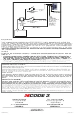
RED - POSITIVE
SWITCH
(USER SUPPLIED)
IN-LINE FUSE
(USER SUPPLIED)
WHITE -
SWITCH
(USER SUPPLIED)
YELLOW -
(SYNC)
BLUE -
MOMENTARY TO
GROUND (FLASH
PATTERN SELECT)/
POSITIVE (DIM ON
WARNING PATTERN
ONLY)
BLACK - GROUND
+ -
POSITIVE
Electrical Connections:
Unit 1, Green Park, Coal Road
Seacroft, Leeds, England LS14 1FB
+44 (0)113 2375340
CODE3ESG
.co.uk
10986 North Warson Road
St. Louis, MO 63114 USA
(314) 996-2800
CODE3ESG
.com
An
ECCO SAFETY GROUP™
Brand
ECCOSAFETYGROUP
.com
439 Boundary Road
Truganina Victoria, Australia
+61 (0)3 8336 0680
CODE3ESG
.com/au/en

