


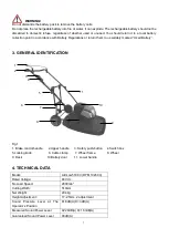


9
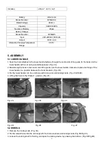
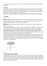
4. Fix the wheel frame into the lower handle and tighten the locking knob. (Fig. 3F)
Fig.3A Fig.3B Fig.3C
Fig.3D Fig.3E Fig.3F
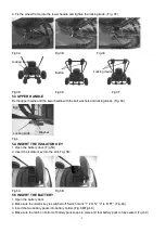
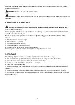
5.3 UPPER HANDLE
Fix the upper handle and the lower handle with the bolt, washers and locking knobs. (Fig. 4A)
Fig.4
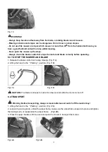
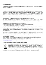
5.4 INSERT THE ISOLATOR KEY
1. Open the battery door. (Fig.5A)
2. Insert the isolator key into the slot. Fig. 5B
)
Fig.5A Fig.5B
5.5 INSERT THE BATTERY
1. Open the battery door.
2. Make sure the isolator key is switched off. Switch mark
”1” is ON”, “0” is “OFF”. (Fig. 6A)
3. Insert the two battery packs into battery holder. (Fig. 6B/Fig.6C)
4. Make sure the latch on bottom of battery pack snaps in place and that battery pack is fully seated. (Fig. 6C)
Wheel frame
Washer
Locking knob
Washer
Locking knob
Bolt
Locking knob
Button
Locking device


