background image

5

Nothing comes close to a Cobra

®

4

English

Quick Evaluation Before Installation

This section provides you with basic information about the inverter and how 
to check its performance before installation.

Be Sure to Have on Hand:

A 12 volt DC power source (such as a vehicle battery).

The power source must provide between 11 and 15 volts 
DC and be able to supply enough current to run the test
load. As a rough guide, divide the wattage of the test load 
by 10 to get the current (in amperes) the power source 
must deliver.

A set of cables to connect the power source to the inverter (not included).

The cables must be as short and thick as possible in order to reduce the voltage 
drop between the power source and the inverter when drawing current from the
power source. 

If the cable suffers an excessive voltage drop, the inverter may shut down when
drawing higher currents because the voltage at the inverter dropped below 10 volts. 

#4 AWG stranded copper cable is recommended. It should be no longer than 
1.5 meters (4 feet). 

The end of the cable that connects to the inverter must have its insulation stripped 
off for about 

1

2

inch (1.25 cm) back from the end, exposing the bare copper. 

The other end of the cable, which connects to the power source, must be
terminated with a lug or other connector that provides a secure, low resistance
connection. 

For example, if the power source is a battery, the cable must be terminated 
with a battery terminal that clamps to the post on the battery.

A test load that can be plugged into the AC receptacle on the inverter for short 
term testing at a low power level. The following cables are recommended for 
testing low power level test loads only.

Test Load Power 

Minimum Cable Size

100w

#16 AWG copper

250w

#12 AWG copper

500w

#8  AWG copper

Quick Evaluation Before Installation

Introduction

Quick Evaluation Before Installation

Introduction

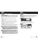
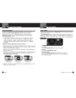
To Check Your Inverter’s Performance Before Installation:

1. Turn the inverter Off (see page 15 for details). 

If the power source is a DC power supply, 
switch it Off as well.

2. Connect cables to Power Input Terminals 

(see page 8 for details).

3. Connect cables to Power Source 

(see page 8 for details).

4. Check to make sure all connections are secure.

5. Turn the inverter On. If the power source is 

a DC power supply, switch it On first.

6. Plug in the test load.

The inverter should supply power to the load. 
If the inverter is not working properly, refer to 
the Troubleshooting Guide on page 21 or Power 
and Protection Indicators section on page 18.

7. Test the GFCI Outlet (see page 16 for details).

Test Load

On/Off Switch to Off

Connect Terminals

Connect Power Source

On/Off Switch to On

Connect Test Load

Test GFCI Outlet

Power Supply

Содержание CPI M 2200

Страница 1: ...duct or not understand its many features please refer to this owner s manual If you require further assistance after reading this manual Cobra Electronics offers the following customer assistance serv...

Страница 2: ...22 Warranty Warranty 23 Customer Assistance Maintenance 24 Product Service 24 Accessories and Order Form 26 Controls Indicators and Product Features Introduction Table of Contents Introduction Featur...

Страница 3: ...atements identify conditions that could result in personal injury or loss of life General Precautions 1 Never install the inverter in a boat s engine compartment where gas and battery fumes are presen...

Страница 4: ...rous voltages are present at the battery terminals This problem does not occur with the vast majority of battery operated equipment Most use a separate charger or transformer that is plugged into the...

Страница 5: ...be terminated with a lug or other connector that provides a secure low resistance connection For example if the power source is a battery the cable must be terminated with a battery terminal that cla...

Страница 6: ...han longer DC wires cables CAUTION To avoid fire do not cover or obstruct ventilation openings Do not install inverter in a zero clearance compartment Overheating may result CAUTION The inverter must...

Страница 7: ...ssential between the battery and inverter This is so it can deliver the maximum amount of energy to the load Use only copper wire Aluminum wire has about 1 3 more resistance than copper wire of the sa...

Страница 8: ...es and should be performed by a qualified electrician CAUTION Do not connect the inverter and another AC source such as a generator or utility power to the AC wiring at the same time The inverter will...

Страница 9: ...r for a specified length of time Example Reserve capacity a battery with a reserve capacity of 180 minutes can deliver 25 amperes for 180 minutes before it is completely discharged Example Ampere hour...

Страница 10: ...the Remote On Off Switch assembly and cable does not interfere with the driver or a passenger Be sure there is adequate clearance behind the panel before drilling or cutting 2 Cut out the mounting te...

Страница 11: ...o turn the inverter On or Off from a convenient location when the inverter is installed in an out of reach location Be sure to have your power inverter and Remote On Off Switch properly installed befo...

Страница 12: ...r and Protection Indicators The Power and Protection Indicators include along with an audible alarm an over temperature indicator an amps meter a volts meter and an overload indicator Over Temperature...

Страница 13: ...ut voltage exceeds 12V 0 3V The inverter will also shut down if the input voltage exceeds 15 75V 0 75V This protects the inverter against excessive input voltage Although the inverter has protection a...

Страница 14: ...rranties of merchantability and fitness for a particular purpose are limited in duration to the length of this warranty Cobra shall not be liable for any incidental consequential or other damages incl...

Страница 15: ...to prevent accumulation of dust and dirt At the same time tighten the screws on the DC input terminals Be sure vents and fans are free of dust or debris Product Service If you have any questions about...

Страница 16: ...y products includes CB Radios microTALK Radios Radar Laser Detectors Safety Alert Traffic Warning Systems Accessories GPS Global Positioning System HighGear Accessories Name Address No P O Boxes City...

Отзывы: