3
-
24
276 Owner’s Manual
COBALT
276
BOWRIDER
S
ECTION
3
3. ENGINE HATCH -
This switch operates the
electric motor box assembly. Do not continue to
operate the switch when the motor box is closed or
fully open. Lower the motor box support after the
motor box is opened. Be sure to return the support
to its stowed position before lowering the box.
4. STEREO REMOTE CONTROL (standard on
dash, transom mount – optional) -
This panel
provides remote control of the stereo system from
the helm.
5. HEATER (Optional) -
This switch operates the
optional cockpit heater blower. It is a four-position
switch: OFF/LOW/MEDIUM/HIGH. Temperature
can be controlled by the switch and by adjusting the
louvered vents. The cockpit heater will only be
effective (warm enough) when the engine is
running at normal operating temperature.
6. SWITCH PANEL
HORN -
This switch activates the horn. Press the
switch to activate.
BILGE PUMP -
This switch manually controls the
bilge pump.
DOCKING LIGHTS (Optional) -
This switch
operates the docking lights.
Docking lights are to be used for docking only. It is
illegal to use your docking lights while cruising.
INTERIOR LIGHTS -
This switch provides
illumination within the cockpit area.
STORAGE and ENGINE COMPARTMENT
LIGHTS -
This switch provides illumination within
the storage areas and engine compartment.
CAPTAIN’S CALL (Optional) -
This switch
determines the routing of the engine exhaust. In the
ON position, engine exhaust is routed through the
thru-hull pipes. This position produces the most
engine power, but is not acceptable near shore or
on inland lakes and rivers.
In the OFF position, engine exhaust is routed
through the hub of the propeller. This position
releases the exhaust underwater, providing a
quieter engine sound.
Be sure to check local regulations regarding noise
restrictions before operating this system.
PLATFORM LIGHTS -
This switch provides
illumination within the platform area.
ACC -
This switch is available to operate switched
accessory items.
INDICATOR LEDS -
The LEDs will illuminate if the
switch is ON.
7. IGNITION SAFETY SWITCH
Your Cobalt boat is equipped with an ignition safety
switch located on the lower lip of the helm. The
ignition safety switch and lanyard will stop the
engine in case of an emergency. Attach the lanyard
to the boat operator whenever the engine is
running, but be aware there will be a loss of boat
control if the switch is activated. If the operator is
thrown from the seat or moves too far from the
helm, the lanyard will become disconnected from
the ignition safety switch, shutting off the engine.
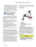
CAUTION
Avoid damage to the exhaust system.
DO NOT switch the routing of the
exhaust above 3,000 RPM.
NOTICE: DO NOT connect an
accessory drawing more than 10
amps to the accessory switch. A
hazardous situation or damage
to the electrical system can
occur.
A
WARNING
Avoid injury, death or damage to
equipment. Do not allow your boat to be
operated without the proper use of the
ignition safety switch and lanyard.
Содержание 276 bowrider
Страница 1: ...COBALT BOATS Owner s Manual 276 OM_Cover_276 indd 1 9 14 08 6 12 24 PM ...
Страница 8: ...vi COBAL T 276 BOWRIDER This Page Intentionally Left Blank ...
Страница 28: ...1 20 276 Owner s Manual COBAL T 276 BOWRIDER SECTION 1 NOTES ...
Страница 96: ...3 40 276 Owner s Manual COBAL T 276 BOWRIDER SECTION 3 NOTES ...
Страница 99: ...276 Owner s Manual 4 3 SYSTEMS FUEL ROUTING COB_0280_A ...
Страница 106: ...4 10 276 Owner s Manual COBAL T 276 BOWRIDER SECTION 4 NOTES ...
Страница 124: ...6 10 276 Owner s Manual COBAL T 276 BOWRIDER SECTION 6 NOTES ...
Страница 127: ...276 Owner s Manual 7 3 REFERENCE AND FORMS SERVICE LOG Date Hour Reading Service Repairs Performed ...
Страница 131: ...Inside_FrontRear_Cover fm Page 1 Wednesday March 1 2006 6 02 AM ...


