background image

1

2) 

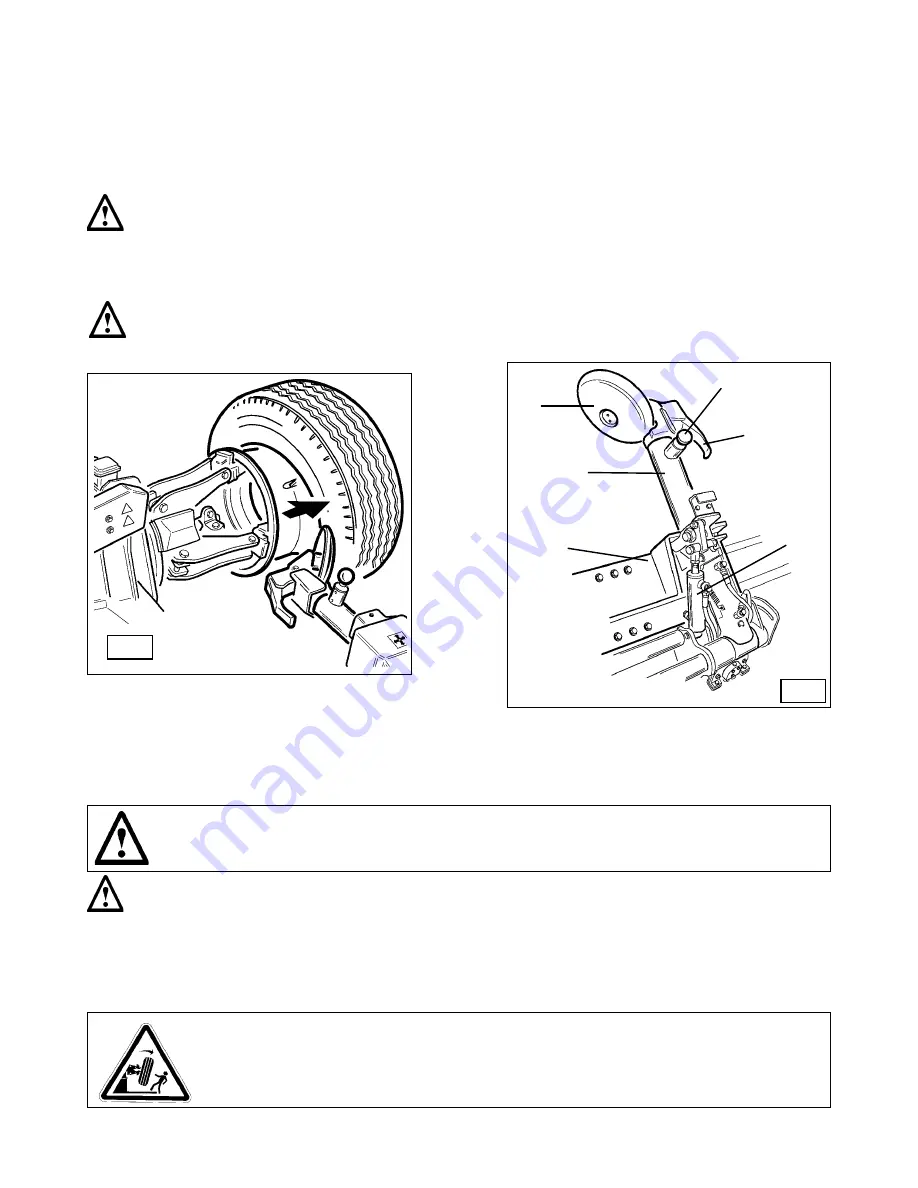
Lower the tool carrier arm 

(14, Fig. D) 

to its work position until its hook has engaged into position on the carriage.

3) 

Use the joystick  to position the wheel so that the bead loosener disk touches up against outside edge of the centre well rim.

4) 

Turn the spindle and at the same time move the bead loosener disk forward until the split-ring is detached. Watch out for the O-ring.

5) 

Repeat this operation but this time move the disk against the split-ring 

(See Fig. Z) 

until the locking ring is released. this ring can be 

removed with the special 


 lever 

(19, Fig. Z) 

or with the help of the bead disk.

6) 

Remove the O-ring

7) 

Move the tool carrier arm

 (14, Fig. D) 

back from the edge of the rim. Release the hook and tip the arm to its non-working position.

Move the tool carrier arm to the inside face of the tire.

8) 

Press lever 

(9, Fig. C) 

and turn the tool head 180° which will automatically lock in this position. Lower the arm to its working position.

9) 

Turn the spindle and at the same time bring the bead loosener disk up against the tyre between the rim and bead. Move the disk 

into the tyre only when the bead has started to detach from the rim, and move the bead to the outside edge of the rim. (

NB: 

Lubricate 

during this process).

10) 

Tip the tool carrier arm to its non-work position.

11) 

Move the ramp 

(4, Fig. A) 

directly under the tire.

Take the mobile control unit to work  position D.

Take the mobile control unit to work  position B.

D

 K

18

1

1

19

17

15

12) 

Lower the spindle until the tire is resting on the ramp.

13) 

Move the ramp towards the outside until the tire together with the split ring comes completely off the rim. 

14) 

Remove the rim from the spindle.

15) 

Position the tire on the platform with the splint ring turned towards the spindle.

16) 

Clamp the split ring on the spindle as explained in the section of RIM CLAMPING.

DANGER!

The tire is not attached to the split ring completely. Any strain on it during positioning or clamping operations could cause 

it to detach and fall.

17) 

Lift the tire assembly.

18) 

Move the tool carrier arm back to its work position.

19) 

Position the spindle so that the bead loosener disk is lined up with the bead.

20) 

Turn the spindle and move the disk forward until the tire comes completely off the split ring.

This double bead breaking procedure can be eliminated by using the 

PAIR OF CLAMPS 

#9299273 (optional) that fix the split-ring to the 

rim so that they are loosened out at the same time. 

DANGER!

When the beads come off the rim, the tire will fall. Check to make sure there are no by-standers in 

the work area.

Take the mobile control unit to work  position D.

Содержание CHD-9551

Страница 1: ...anger For Medium and Large Size Tires CHD 9551 READ these instructions before placing unit in service KEEP these and other materials delivered with the unit in a binder near the machine for ease of re...

Страница 2: ...FICATION OF CONTROL 9 11 WORKING POSITION 9 12 CORRECT OPERATION CHECKS 9 13 OPERATION 11 13 1 Locking the wheel 11 Light alloy rim locking 13 2 Tubeless and supersingle wheels 12 Bead breaking Demoun...

Страница 3: ...to specially trained and authorized personnel Any unauthorized changes or modifications to the machine in particular to its electric system relieve the manifacturer from all liability Removing or tamp...

Страница 4: ...ive humidity from 30 95 without condensation Temperature from 32 131 F 0 55 C UNPACKING 7 1 INSTALLATION PLACE ATTENTION The machine must not be operated in explosive atmospheres Maximum machine space...

Страница 5: ...ing through the holes provided on the base frame If there is an additional floor covering B or if shims or wedges are necessary for levelling C longer anchor bolts must be used Place an anchor bolt in...

Страница 6: ...ighted on the data plate fixed to the tire changer Check to make sure the shop electric wiring circuit is dimensioned sufficiently to carry this Work on the electric system even if minor must be done...

Страница 7: ...4 Sliding ramp 5 Switch 8 Handler 9 Switch 10 Pedal 11 Handler 13 Carriage 14 Tool holding arm 15 Arm lever 17 Bead breaking disk 18 Tool 19 Arm locking cylinder 22 Jaw WARNING During all operations...

Страница 8: ...e and missing warning labels must be replaced immediately Do not use the tyre changer if one or more labels are missing Do not add any object that could prevent the operator from seeing the labels Use...

Страница 9: ...fig C when moved upwards turns the tool with disc towards the spindle and when moved down ward turns the tool with the fingen towards the spindle 17 fig D or 18 fig D The pedal 10 fig C when pressed o...

Страница 10: ...s 3 Fig A should open move the lever down and the spindle arms should close 3 Depress the right pedal 10 Fig C the spindle 3 Fig A should turn clockwise depress the left pedal the spindle should turn...

Страница 11: ...bly on the sliding ramp to the self centering chuck Operate the chuck switch 5 fig C to open the self centering chuck and clamp the inner side of the rim E 2 E 3 E 4 E 5 The most convenient clamping p...

Страница 12: ...GER The bead loosener disk must NOT be pressed against the rim but against the tire bead 5 Rotate the wheel and at the same time advance the loosener disk plate with small forward movements following...

Страница 13: ...h against the inside plane of the tire until both beads come off the rim See Fig H Always keep the tire rotating while pushing with the bead disck 2 With Supersingle or very hard tires the procedure d...

Страница 14: ...bead loosener disk If the tire is very rigid the hook tool must be used TIRE MOUNTING WITH THE DISK Follow these steps 1 If the rim has been removed from the spindle put it back on the spindle as des...

Страница 15: ...ove the g clamp Take the mobile control unit to work position C 13 Close the arms of the spindle completely Support the tire assembly to prevent it falling off DANGER Potentially hazardous operation D...

Страница 16: ...Fig C 10 Attach the g clamp at the bottom 6 o clock outside the second bead See Fig N Take the mobile control unit to work position C 11 Turn the spindle counterclockwise to about 90 clip at 9 o clock...

Страница 17: ...B P D 18 14 13 19 17 15 Take the mobile control unit to work position D 10 Move the tool carrier arm to the inside face of the tire turn the hook tool 180 and lower the arm to its work position Insert...

Страница 18: ...mp is at the bottom 6 o clock The first bead will be on the rim Remove the g clamp Take the mobile control unit to work position D 10 Remove the tool from the tire 11 Move the tool carrier arm to its...

Страница 19: ...l See Fig V This lever can be supplied on demand 24 Pull back on this lever which will guide the bead into drop center Continue to turn the spindle until the tire is completely mounted on the rim 25 R...

Страница 20: ...lever 19 Fig Z or with the help of the disk 7 Remove the split ring 8 Move the tool carrier arm 14 Fig D back from the edge of the rim Release the hook and tip the arm to its non working position Move...

Страница 21: ...bricate during this process 10 Tip the tool carrier arm to its non work position 11 Move the ramp 4 Fig A directly under the tire Take the mobile control unit to work position D Take the mobile contro...

Страница 22: ...orward with the spindle turning until it is completely inserted 7 Put the split ring on the rim and then install the locking ring with the help of the disk as shown in Fig Y 8 Move the tool carrier ar...

Страница 23: ...rmed only after the disconnetion of the plug from electric network To ensure that this tire changer works perfectly over the years carry out the routine maintenance schedule described below 1 Lubricat...

Страница 24: ...st 2 5 inches 60 mm wide and of a lenght sufficient to bring the hook of the belt above the tyre changer 5 With the special belt ring bring the 2 ends of the belt together and lift with a sufficiently...

Страница 25: ...nufacturer information 2 Model 3 Serial number 4 Phases 5 Voltage requirements 6 Frequency 7 Rated draw 8 Year 9 Weight 10 Absorbed power 19 DATA ON SERIAL PLATE Type Volt Amp 5 7 Kw 10 Hz 6 2 Nr 3 Ph...

Страница 26: ...HENNESSY Industries INC 1601 J P Hennessy Drive LaVergne TN 37086 USA Toll Free 800 688 6496 www ammcoats com...

Отзывы: