


Education Robot
47
System Block Diagram
Overall structure is divided into ATmega128 and ATmega88, there is a serial
port (RS232c) for wired connection and Bluetooth module for wireless com-
munication. For communication robot uses SPI protocol. The control board uses
external 9V DC power supply, for powering each module separately control
board includes 5V line and 3.3 V regulator. I/O and A/D operates separately
from processor (128, 88).
First, user should download firmware via USB to ISP communication cable and
then set up Dot Matrix, Buzzer, DC Motor Drive, Encoder, Function buttons (5
I/O modules), IR and PSD sensor (2 A/D models). Atmega 88 processor can’t be
edited by the user. It contains default LED (1 I/O module) and 4 A/D modules
(Mice, Battery check, IR and circuit check setups).
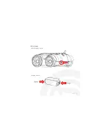
Содержание CRX10
Страница 4: ...Education Robot 38 CRX10 structure CRX10 Description Front and side view y GRG G G i i G jkTyvt t...
Страница 12: ...Education Robot 46 System Block Diagram...
Страница 17: ...Education Robot 51 Charging Method CRX10 charging CRX10 charging scheme...
Страница 31: ...Education Robot 65...