background image


AN113 


Rev 1.0 | Page 6/34 

www.hoperf.com 

2.  Application Schemes 

In order to help to user to start using the Development Kits easily, CMOSTEK has defined a few configurations with different 

application schemes on the RFPDK. The user only needs to follow the guidelines in the subsections of this chapter, program 

the configuration to the corresponding evaluation modules and start the evaluation. The application schemes are listed in the 

tables below with the different modules required. 


Table 2. Application Schemes for CMT2150A-EM in Pair with CMT2250A-EM 

Application 

Schemes 

CMT2150A 

CMT2250A


Description 

Basic/Advanced 

Index 

Basic/Advanced 

Index 

LED On/Off


Basic 

Basic 

To control the LEDs on CMT2250A-EM in On/Off 

manner


Pulse


Basic


Basic


To control the LEDs on CMT2250A-EM in Short 

Pulse manner


Periodic Tx


Advanced


Advanced


Periodic transmission from CMT2150A-EM to 

CMT2250A-EM 


Table 3. Application Scheme for CMT2150A-EM in Pair with CMT2251A-EM 

Application 

Schemes 

CMT2150A 

CMT2251A


Description 

Basic/Advanced 

Index 

Basic/Advanced 

Index 

PWM


Advanced 

Advanced 

To control the LED on the CMT2251A-EM with 

PWM signal generated by the CMT2251A


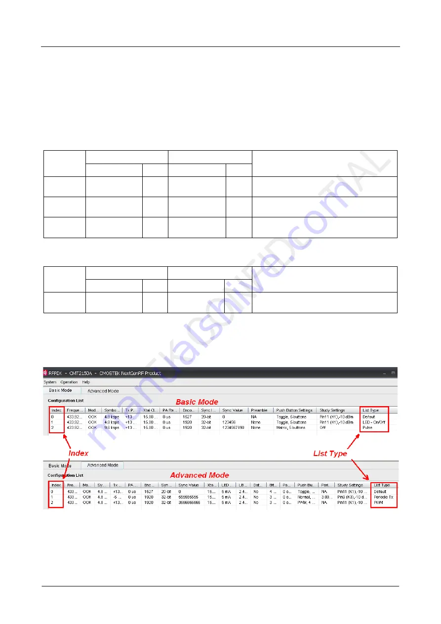
The configurations of each application scheme are by default provided on the RFPDK. The Index number is shown in the 1

st


(left) column of the configuration list, while the name of the application list (also called “List Type”) is shown in the last (right) 

column. An example of the CMT2150A configuration lists in Basic / Advanced modes are shown in the figures below. 


Figure 3. Configuration Lists of the CMT2150A 


After  selecting and  programming the application scheme into the devices, the corresponding functions can be immediately 

demonstrated. Those functions are introduced in the below sub-sections. 

Содержание CMT2 5 Series

Страница 1: ...ns CMT2251A True single chip ultra low power and high performance device that consists of an OOK RF receiver a data decoder and 1 PWM output pin for various 300 to 480 MHz wireless applications The De...

Страница 2: ...Connector 23 6 2 LED Indicators 23 6 3 USB Socket 24 7 RFPDK 25 7 1 Installation Steps 25 7 2 Starting the RFPDK 25 7 3 Device Control Panel 27 7 3 1 Basic Mode and Advanced Mode 27 7 3 2 Configuratio...

Страница 3: ...rcuit Board BOM Bill of Materials PER Packet Error Rate CDROM Compact Disk Read Only Memory PWM Pulse Width Modulation EM Evaluation Module s RF Radio Frequency Err Error RFPDK RF Products Development...

Страница 4: ...x USB Programmer V1 1 x CDROM with RFPDK installer and documents 1 x USB Cable 6 x AA Batteries 3 x Antennas Please note that the CMT2150A EM is by default configured to work in pair with CMT2250A EM...

Страница 5: ...dule The user can use it to evaluate the CMT2251A PWM control feature RFPDK CMOSTEK provides the PC application that allows the users to configure all the product features to CMOSTEK NextGenRFTM produ...

Страница 6: ...0A EM in Short Pulse manner Periodic Tx Advanced 1 Advanced 1 Periodic transmission from CMT2150A EM to CMT2250A EM Table 3 Application Scheme for CMT2150A EM in Pair with CMT2251A EM Application Sche...

Страница 7: ...uld be used as Off button if the On Off button s is set as Separated on the RFPDK K3 K4 K5 K6 Turn on and off the LED1 LED2 LED3 and LED4 on CMT2250A EM respectively The user can follow below instruct...

Страница 8: ...rmat 2 The study function is enabled in this scheme while the Sync ID on both of the Tx and Rx side are set to the same by default In order to experience the study function the user should set the Syn...

Страница 9: ...cable then start the RFPDK on the PC 2 Connect the CMT2150A EM to the USB Programmer with EM Connector select CMT2150A on the RFPDK stay in Basic Mode select the Pulse configuration on the configurat...

Страница 10: ...pressed the largest number of buttons can be pressed at the same time is 2 2 In the LED part Pulse represents that the LED is turned on for 2 seconds and then turned back to off while 0 represents tha...

Страница 11: ...stall the latest RFPDK on the PC refer to Section 7 1 Installation Steps and connect the USB programmer to the PC with a USB cable then start the RFPDK on the PC 2 Connect the CMT2150A EM to the USB P...

Страница 12: ...nds Study Function on Study Button Pin9 K3 Notes 1 Please refer to the AN112 CMT2150A Configuration Guideline for the introduction of Normal mode of the push button setting and the 1920 encoding forma...

Страница 13: ...with a USB cable then start the RFPDK on the PC 2 Connect the CMT2150A EM to the USB Programmer with EM Connector select CMT2150A on the RFPDK select the Advanced Mode select the PWM configuration on...

Страница 14: ...mal scheme by setting the Button Mode on the RFPDK to Normal In this scheme each LED on the CMT2250A EM is controlled by one push button on the CMT2150A EM respectively The push buttons are shown and...

Страница 15: ...EM can be used in normal scheme with the following items to be noticed 1 Since the push button which should be connected to Pin12 K0 is not designed on the CMT2150A EM V1 0 with the configuration ste...

Страница 16: ...3 Rev 1 0 Page 16 34 www hoperf com Figure 18 Configuring Data Pin Reset Code of the CMT2250A The user can refer to AN112 CMT2150A Configuration Guideline for more information about the Normal button...

Страница 17: ...pin 2 54 mm male connector used to connect to the USB Programmer 2 Power Mode Switch The power mode Switch S1 is used to select the power supply source of the module The module can be supplied by the...

Страница 18: ...assigned as increase and decrease buttons 5 In Toggle and PWM modes if On Off Button s on the RFPDK are set to Single only K1 is used as on and off button if On Off Button s is set to Separated K1 is...

Страница 19: ...the power supply source of the module The module can be supplied by the battery S1 switched to the VBAT side or the EM Connector S1 switched to the VEXT side It is recommended to put the switch to th...

Страница 20: ...modes and periodic transmission The evaluation module contained in this Development Kits is designed with the matching network at 433 92 MHz For application with different frequencies the matching ne...

Страница 21: ...to select the power supply source of the module The module can be supplied by the battery S1 switched to the VBAT side or the EM Connector S1 switched to the VEXT side It is recommended to put the swi...

Страница 22: ...modes and periodic transmission The evaluation module contained in this Development Kits is designed with the matching network at 433 92 MHz For application with different frequencies the matching ne...

Страница 23: ...r The EM Connector on the USB Programmer is 10 pin 2 54 mm female connector as shown below 2 4 6 8 10 9 7 5 3 1 Figure 26 EM Connector Table 14 Pin Descriptions of EM Connector Pin Number Pin Function...

Страница 24: ...programmed Green Err Turned on for 5 seconds when the programming has failed Red USB Turned on when the USB is correctly connected to the PC Green 6 3 USB Socket The USB Programmer contains a type B...

Страница 25: ...oft Windows Start button by clicking Start All Programs CMOSTEK RFPDK CMOSTEK RFPDK V1 01 Figure 30 Starting RFPDK from PC Desktop Once the program has started the device selection panel of the RFPDK...

Страница 26: ...AN113 Rev 1 0 Page 26 34 www hoperf com Figure 31 Device Selection Panel Select the proper device and then click Next the Device Control Panel appears as below Figure 32 Device Control Panel...

Страница 27: ...o select predefined chip configuration from the list including the default configurations provided by CMOSTEK or the customized configurations save by the user For the non default configurations the u...

Страница 28: ...device is connected but the USB Programmer is in Unconnected status Device CMT2150A The device plugged in is different from that selected in the Device Selection Panel The part number of the plugged...

Страница 29: ...ser asks for any technical support 7 5 Read Device When the device the USB Programmer and the PC RFPDK are properly connected the Read Device function can be used to read out and upload the EEPROM con...

Страница 30: ...close the RFPDK before plugging out the USB Programmer and then reboot the PC to resolve this problem Q3 Can I install the RFPDK on a PC on which I don t have administration right A3 CMOSTEK recommen...

Страница 31: ...AN113 Rev 1 0 Page 31 34 www hoperf com 9 Document Change List Table 18 Document Change List Rev No Chapter Description of Changes Date 1 0 Initial version 2014 08 13...

Страница 32: ...AN113 Rev 1 0 Page 32 34 www hoperf com 10 Appendix CMT2150A EM and CMT2250 1 A EM Schematics Figure 35 CMT2150A EM Schematic Figure 36 CMT2250A EM Schematic...

Страница 33: ...AN113 Rev 1 0 Page 33 34 www hoperf com Figure 37 CMT2251A EM Schematic...

Страница 34: ...y is assumed for inaccuracies and specifications within this document are subject to change without notice The material contained herein is the exclusive property of CMOSTEK and shall not be distribut...

Отзывы: